Optical termination assemblies

a technology of optical termination and assembly, which is applied in the direction of optics, instruments, optical light guides, etc., can solve the problems of disadvantageous installation of one of the above known optical termination boxes, inconvenient installation for the end user, and long installation time so as to prevent damage to the content, reduce the number of steps performed by the operator within the apartment of the end user, and short time

Active Publication Date: 2016-07-05
PRYSMIAN SPA
View PDF50 Cites 1 Cited by
  • Summary
  • Abstract
  • Description
  • Claims
  • Application Information

AI Technical Summary

Benefits of technology

[0014]In particular, the Applicant has tackled the problem of providing an optical termination assembly comprising an optical termination box and a drop cable, whose installation requires a minimum number of steps to be performed by the operator in the apartment of the end user, and that allows minimizing the risk of damaging the content of the optical termination box during installation.
[0020]Advantageously, the number of steps performed by the operator within the apartment of the end user is reduced. Since the drop cable is pre-connectorized, the operator merely has to fix the optical termination box to the support structure, and does not have to make optical fiber splices and arrange optical fibers, optical fiber splices and optical connectors in the optical termination box while he is in the apartment of the end user. Accordingly, the installation of the optical termination box in the apartment of the end user can be completed in a very short time, and is then less inconvenient for the end user.
[0021]Further, the risk that the operator damages the content of the optical termination box during installation is advantageously minimized.
[0022]Indeed, handling of optical fiber splices, optical fibers and optical connectors by the operator is advantageously avoided. Further, the operator does not have to open the optical termination box for fixing it to the support structure. Then, the operator is prevented from damaging the content of the box while he performs this operation. Further, possible dust and / or wall fragments produced while the operator performs installation can not enter the optical termination box, and accordingly can not damage its content.
[0023]Besides, that fact that the steps of making optical fiber splices and arranging optical fiber splices, optical fibers and optical connectors are performed by the manufacturer that assemblies the optical termination assembly advantageously provides an improved control of these steps. Indeed, these steps may be performed in a controlled environment (e.g. controlled temperature / humidity, controlled pollution level, etc.) by specialized staff at the manufacturer's premises. The optical performance of the optical termination box (e.g. the optical fiber splice losses, the bending losses, etc.) may be therefore optimized, while the risk that an optical termination box having degraded optical performance is installed in the apartment of an end user is advantageously minimized.

Problems solved by technology

Therefore, installing one of the above known optical termination boxes disadvantageously requires performing a number of operations within the apartment of the end user.
Accordingly, the installation time within the apartment of the end user is disadvantageously long (typically, about half an hour).
The installation may then be inconvenient for the end user.
Indeed, optical fibers, optical fiber splices and connectors are very delicate, and they should be accordingly handled very carefully.
If the operator is not skilled or not careful enough, he may disadvantageously damage them during installation.
The risk of damaging the content of the optical termination box is even higher while the operator drills the holes and fixes the base plate to the wall.
For instance, the operator may inadvertently break an optical fiber splice or pierce an optical fiber while he screws the base to the wall.
Further, dust and / or wall fragments produced while the operator drills the holes may fall onto the base, and may damage the optical fibers, the optical fiber splices or the optical connectors arranged on the base.

Method used


Image

  • Optical termination assemblies
  • Optical termination assemblies
  • Optical termination assemblies

Examples


Embodiment Construction

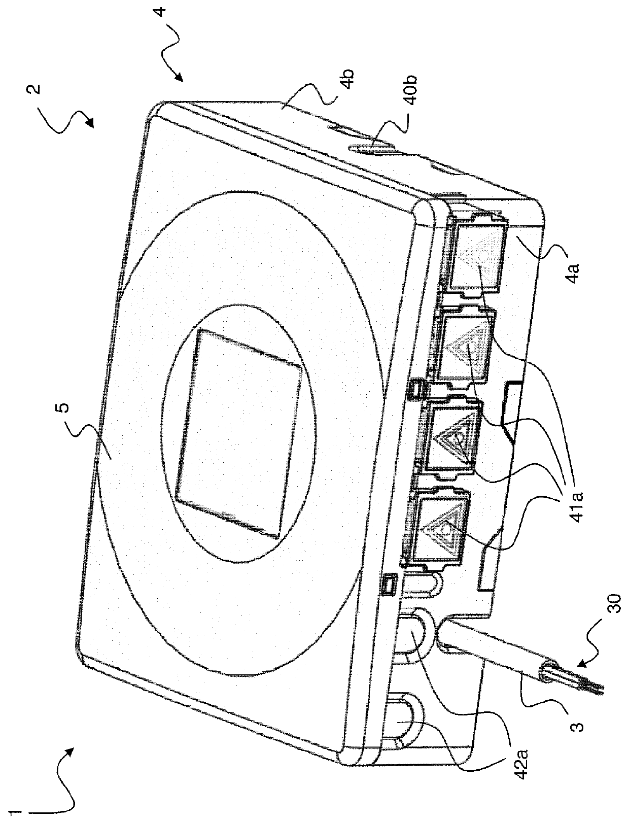
[0051]The Figures (that are not in scale) show an optical termination assembly 1 as assembled and sold by a manufacturer, i.e. before installation in an apartment of an end user.

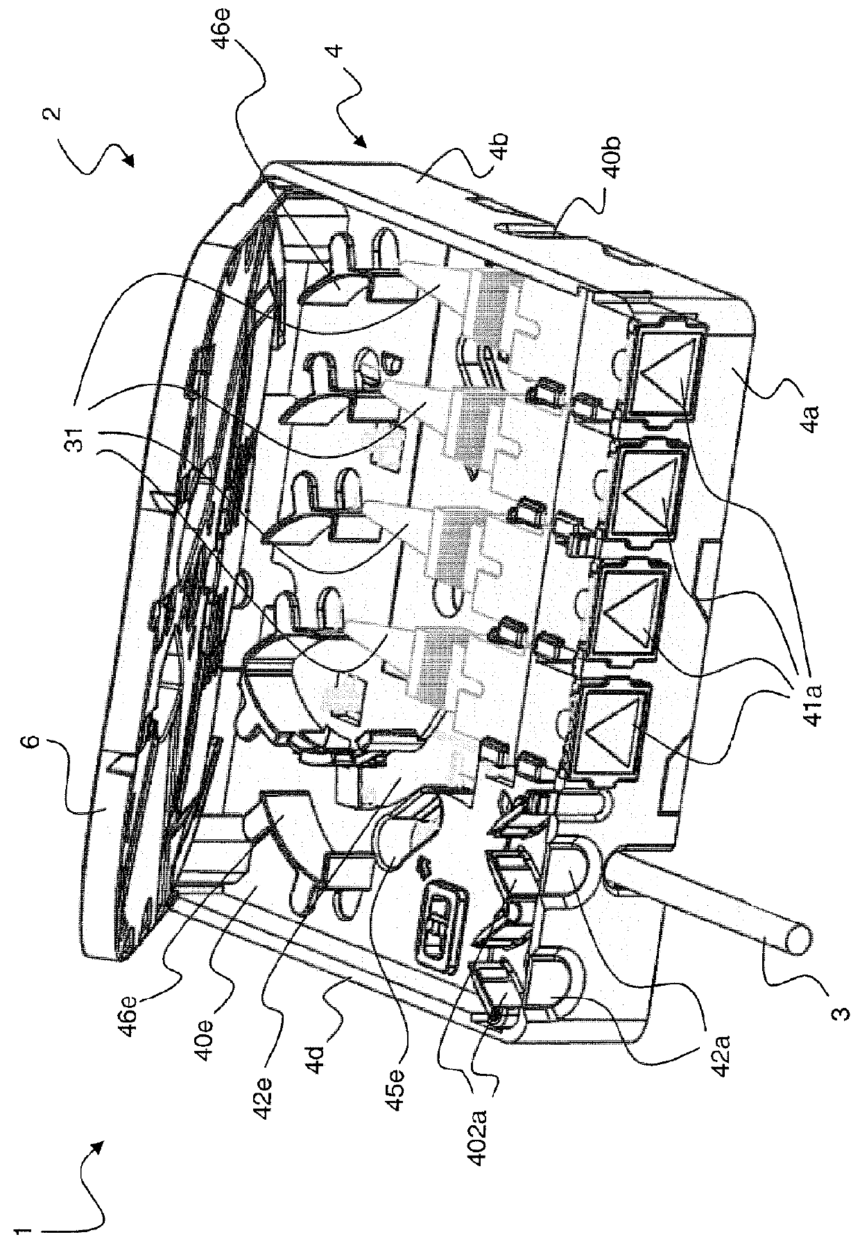
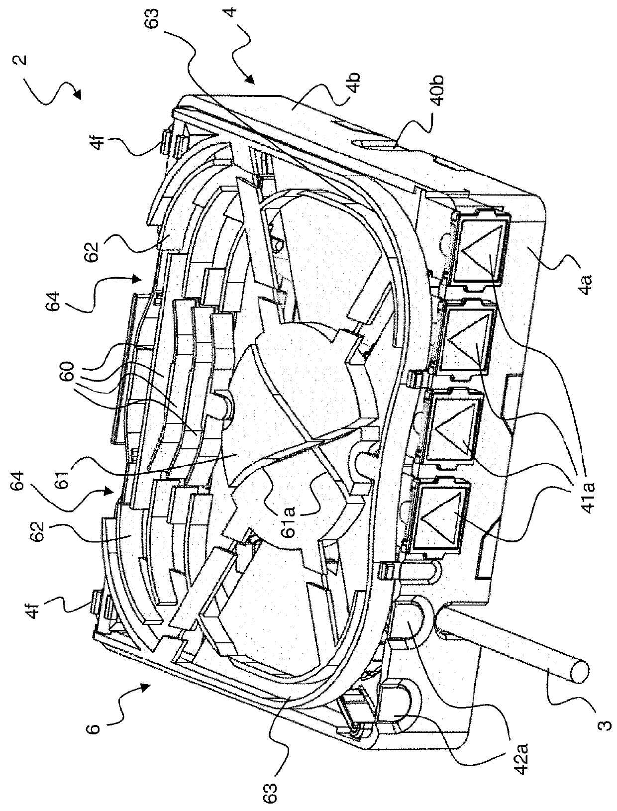
[0052]The optical termination assembly 1 comprises an optical termination box 2 and a drop cable 3. The optical termination box 2 comprises a base 4, a cover 5 and optionally a splice tray 6.

[0053]The base 4 comprises a bottom 4e and four sidewalls 4a, 4b, 4c, 4d. The bottom 4e is substantially rectangular. The sidewalls 4a, 4b, 4c, 4d are substantially perpendicular to the bottom 4e. The bottom 4e has a first surface 40e facing the cover 5 and the splice tray 6 and a second surface 41e opposite to the first surface 40e. The bottom 4e is positioned so that its first surface 40e forms a first compartment together with the four sidewalls 4a, 4b, 4c, 4d, while its second surface 41e forms a second compartment together with the four sidewalls 4a, 4b, 4c, 4d. The first compartment is visible in FIG. 2, while the ...


PUM


Abstract

An optical termination assembly may include an optical termination box and a drop cable. The drop cable may have a first end housed in a first compartment of the optical termination box. The first end of the drop cable may be pre-connectorized. The optical termination box may include at least one first fixing element accessible from an outside of the optical termination box suitable for fixing the optical termination box to a support structure. An optical termination assembly may include an optical termination box and a drop cable including a plurality of optical fibers. The drop cable may have a first end housed in a first compartment of the optical termination box. At the first end of the drop cable, each of the plurality of optical fibers may be connected to a respective optical connector. The optical termination box may include the at least one first fixing element.

Description

CROSS-REFERENCE TO RELATED APPLICATION(S)[0001]This application is a national stage entry from International Application No. PCT / EP2009 / 067852, filed on Dec. 23, 2009, in the Receiving Office of the European Patent Office, the entire contents of which are incorporated herein by reference.TECHNICAL FIELD[0002]The present invention relates to the field of optical access networks. In particular, the present invention relates to an optical termination assembly, the optical termination assembly including an optical termination box and a drop cable. Furthermore, the present invention relates to a method for installing an optical termination assembly.BACKGROUND ART[0003]FTTH (Fiber To The Home) network is an optical access network providing a number of end users with communication services, e.g. with services requiring data transmission at a rate of some hundreds of Mbit / s or more.[0004]Typically, FTTH network comprises a distribution cabinet located in the basement of the building where t...

Claims


Application Information

Patent Timeline
Patent Type & Authority Patents(United States)
IPC IPC(8): G02B6/36G02B6/44
CPCG02B6/4441G02B6/4454
Inventor ABBIATI, FABIOGRIFFITHS, IAN JAMESLE DISSEZ, ARNAUD
Owner PRYSMIAN SPA
Why Eureka
Try Eureka