Cable positioning arrangement

a positioning arrangement and cable technology, applied in the direction of cable installation apparatus, application, show stands, etc., can solve the problems of increasing the time and cost of manufacturing the building, consuming installation, waste of materials,

Active Publication Date: 2016-07-05
JONES WARREN NIGEL
View PDF43 Cites 3 Cited by
  • Summary
  • Abstract
  • Description
  • Claims
  • Application Information

AI Technical Summary

Benefits of technology

[0006]The present invention seeks to mitigate or remove at least one of the above-mentioned problems. The present invention seeks to provide an improved arrangement for positioning cables.
[0007]The present invention provides a cable positioning arrangement comprising a flexible member extending between two structures, the flexible member being associated with a hole through which a cable passes thereby positioning the cable relative to the structures. Using a flexible member tends to enable a number of advantages. For example, a flexible member may be quickly and easily fixed in and out of position, or temporarily moved out of position, thus not causing an obstruction, a flexible member tends to be less voluminous than, for example a wooden noggin, and a large length of flexible member may be easily transportable.
[0015]The flexible member may be under tension. Having the flexible member under tension tends to give it improved structural rigidity. The position of the hole (and thus the cable) may therefore be more stable. The flexible member may be elastic. It will be appreciated that an elastic flexible member not only covers embodiments in which the flexible member is made purely from an elastic material, but also encompasses embodiments in which the flexible member comprises an elastic portion such that the flexible member is elasticated. The flexible member may be elastically extended between the two structures. An elastic flexible member tends to be easily put under tension during installation. The elastic flexible member may have a relatively low elastic modulus. An elastic flexible member may also be advantageous because it can take up relatively little space when not under tension. Thus, when the cable no longer needs to be positioned (for example after a plaster board has been installed in an embodiment in a stud wall), or when the flexible member will interfere with another fitting, the flexible member may be cut, allowing it to contract back to a relatively short, unloaded, state. An elastic flexible member may also be readily pulled out of the way if necessary (for example to access something close to the flexible member).
[0018]One of the structures may comprise a hook. The flexible member may be mounted on the hook. The hook may be arranged to pierce the flexible member. The flexible member may include a hole for mounting onto the hook. Alternatively or additionally, an edge of the flexible member may comprise a cut-out for receiving the hook. The hook may be an integral part of the structure, but is more preferably mounted on the structure. The flexible member may be attached to a bracket mounted on the structure. The hook may be part of the bracket. The flexible member may be supplied with one or more brackets to facilitate easy installation.
[0022]The flexible member may include indicators for identifying the holes (for example the holes may be numbered). The indicators may be arranged to identify the longitudinal and / or lateral position of the hole. Such an arrangement facilitates fast and correct identification of the hole through which the cable should be passed.
[0027]The hole may generate a stress concentration in the flexible member. It is desirable to prevent the flexible member splitting at these stress concentrations. The flexible member may comprise a reinforcement element running along the length of the flexible member to inhibit lateral splitting of the flexible member. The reinforcement element may comprise a multiplicity of discrete parts, but is preferably continuous. The reinforcement element is preferably arranged to inhibit any tears in the flexible member from spreading across the element. The reinforcement element may, for example, be a fibre running along the length of the flexible member. The flexible member may comprise a multiplicity of parallel reinforcement elements running along the length of the flexible member.

Problems solved by technology

It is difficult to ensure the correct position of the cable is maintained once it has been left close to the required position by the electrician; the plasterer often makes a hole and pulls the cable through in the wrong place.
This increases the time and cost of manufacturing the building.
The noggin may be used to better position the cable, but tends to be time consuming to install and wasteful of materials, and is therefore costly.
However, the wooden support of GB 2210914 may be difficult to install and may only be useable for specific geometries.
The difficulty of positioning cables is also an issue in other industries or applications.
For example, electrical apparatus requiring a multiplicity of cables, such as computer servers, or televisions, are often associated with a complicated and untidy collection of input and output cables.
These structures tend to be cumbersome and can obstruct access to other areas.

Method used


Image

  • Cable positioning arrangement
  • Cable positioning arrangement
  • Cable positioning arrangement

Examples


first embodiment

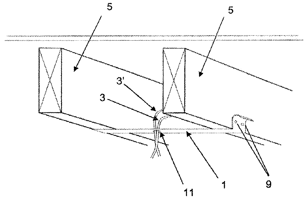
[0052]FIG. 1 is a perspective view of a cable positioning arrangement according to the invention. The arrangement comprises a band 1, an electrical cable 3 and two parallel ceiling joists 5. The ceiling joists 5 are part of the ceiling of a building (not shown). The band comprises a central hole 11 through which the cable 3 passes. A second cable 3′, of the same diameter, also passes through the hole 11.

[0053]By passing the cables 3, 3′ through the hole in the tape, the position of the cables (at least where they pass through the hole) is thereby fixed, relative to the joists 5. Fixing the position of the cables relative to the joists is useful because it enables a ceiling panel fitter to correctly position a hole for the cables in the ceiling panel (not shown) when that ceiling panel is fitted to the ceiling.

[0054]The method of installing the band 1 and positioning the cables 3, 3′ is described in detail below. As is known in the prior art, an electrician firstly installs cables 3,...

second embodiment

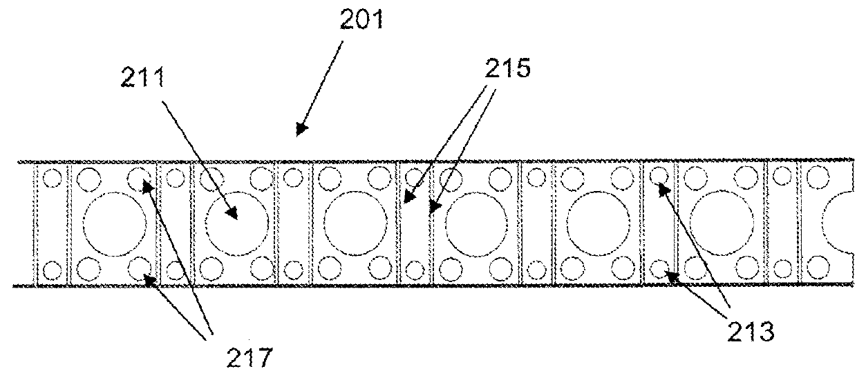
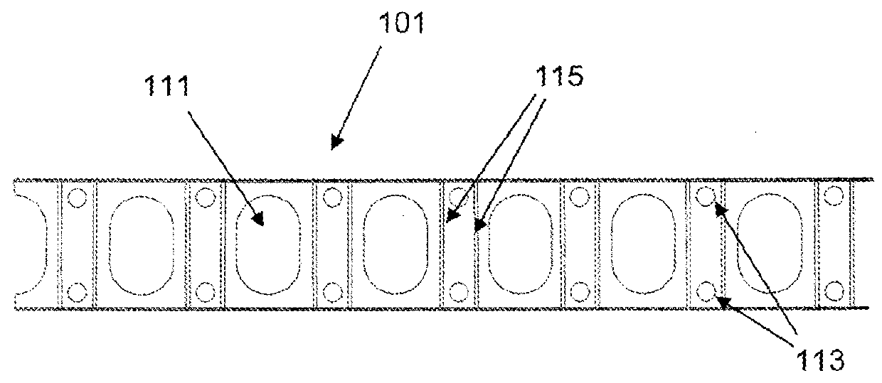
[0058]FIG. 2a is a plan view of a section of elastic band 101 according to the invention. The band comprises a multiplicity of obround holes 111 regularly spaced in a line along the length of the band. Each hole 111 is able to receive several cables (not shown) simultaneously. The band is supplied in a roll and the user simply cuts the required length before attaching the band to a structure.

[0059]Having regularly spaced holes along the length of the band, enables the user to position different cables at different positions along the band 101 (and therefore at different positions between structures). It also means that the user does not need to ensure the single hole is a particular distance (for example half-way) along the band prior to attachment, as is the case in the first embodiment.

[0060]The band 101 includes pairs of small, fastener holes 113 located near the edge of the band, and between the large cable holes 111. The fastener holes 113 are arranged to be able to receive nai...


PUM

PropertyMeasurementUnit
lengthaaaaaaaaaa
widthsaaaaaaaaaa
widthsaaaaaaaaaa

Abstract

A cable positioning arrangement comprises a flexible member, such as an elastic band or cord, extending between two structures. The flexible member is associated with a hole through which a cable passes thereby positioning the cable relative to the structures.

Description

TECHNICAL FIELD[0001]The present invention relates to a cable positioning arrangement and a method of positioning a cable.BACKGROUND OF THE INVENTION[0002]During construction of a building, cables are positioned into the areas needed for electrical fittings such as switches, sockets, ceiling pendants, downlighters and alike. Cables are typically left hanging in approximately the right place by the electricians, especially for what are commonly known as “fast-fix” installations, or flush mounted fittings such as downlighters. For example, the electrician may leave a cable hanging between stud uprights or ceiling joists, for subsequent attachment to an electrical fitting. A covering (for example plaster board) for the wall or ceiling is typically installed by a different operative (for example a plasterer or plaster boarder). When the operative installs the covering they are also required to make holes in the covering and pull the cable through in the required position.[0003]It is dif...

Claims


Application Information

Patent Timeline
Patent Type & Authority Patents(United States)
IPC IPC(8): H02G1/00H02G3/12H02G3/30
CPCH02G1/00H02G3/125H02G3/30Y10T29/49826Y10T29/49874
Inventor JONES, WARREN NIGEL
Owner JONES WARREN NIGEL
Why Eureka
Try Eureka