Outer sleeve and blank therefor

a technology for applied in the field of outer sleeves and blanks, can solve the problems that neither the complete laminate film nor the selective application of film strips will detract from the aesthetic appearance of the package, interfere with printability or any other desirable display features, etc., to achieve the effect of improving the impenetrability of the sleeves, preventing tear propagation, and increasing tear resistan

Active Publication Date: 2016-07-12
WESTROCK MWV LLC
View PDF7 Cites 5 Cited by
  • Summary
  • Abstract
  • Description
  • Claims
  • Application Information

AI Technical Summary

Benefits of technology

The patent text describes a package design that improves its barrier to tearing and prevents tear propagation. This is achieved by laminating a polymer film onto at least one side of the package blank, which makes the exterior of the package more resistant to tearing. The lamination can involve the entire surface of the blank or just specific areas like tear-prone regions or stress points. The lamination does not detract from the package's aesthetic appearance or interfere with printability or any other desirable display features. The package also includes a stop feature and a catch feature to prevent the internal slide cards from being completely pulled away from the outer sleeve. Other measures to improve the package's structural integrity may also be employed such as lamination of the slide card with a polymeric film.

Problems solved by technology

Preferably, neither the complete laminate film nor the selectively applied film strips will detract from the package's aesthetic appearance or interfere with printability or any of the other desirable display features.

Method used


Image

  • Outer sleeve and blank therefor
  • Outer sleeve and blank therefor
  • Outer sleeve and blank therefor

Examples


first embodiment

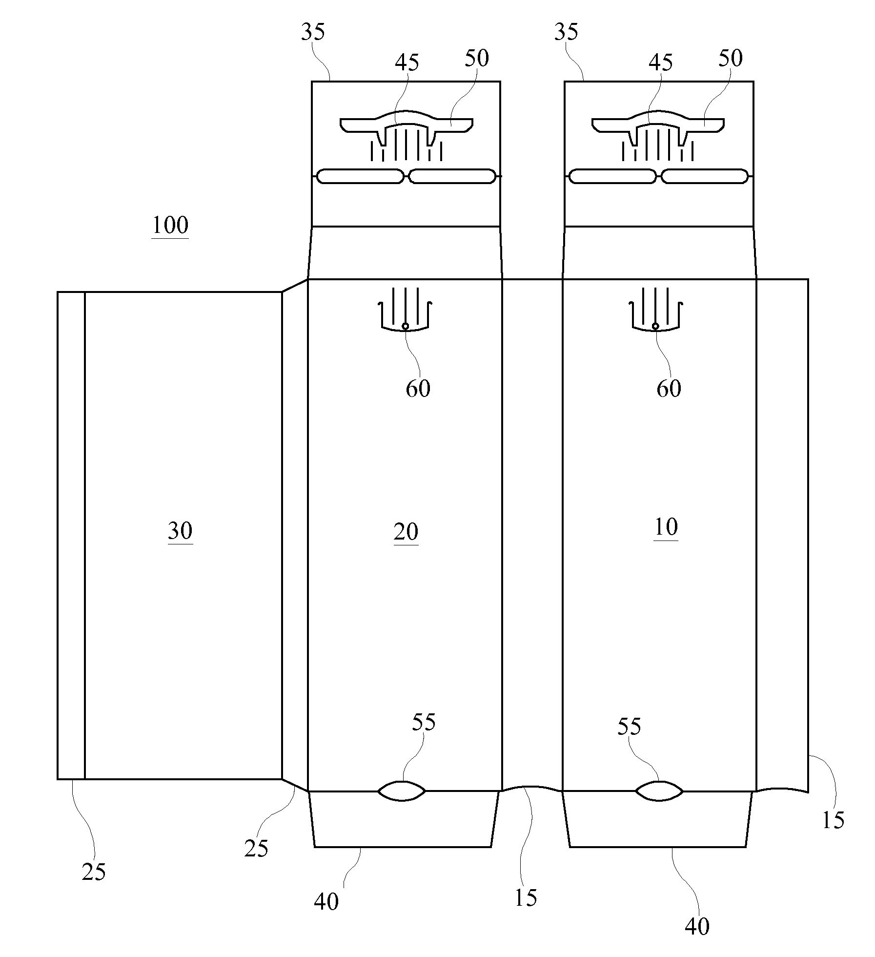
[0016]FIG. 1 is a plan drawing of an outer sleeve according to a An outer sleeve is formed from a blank 100 that is scored to form a pair of side panels 10, 20, an inner partition panel 30, a pair of hinge panels 15, a pair of inner partition hinge panels 25, a first pair of scored extension panels 35, and a second pair of extension panels 40.

[0017]To form the outer sleeve, one of the inner partition hinge panels 25 is folded at a right angle to side panel 20. The inner partition panel 30 is then folded at a right angle to the folded inner partition hinge panel 25 such that inner partition panel 30 is parallel to and beneath side panel 20. The other inner partition hinge panel 25 is then folded at a right angle downward from the inner partition panel 30. Next, the hinge panel 15 that is coupled with both side panels 10, 20 is folded at a right angle downward. This hinge panel 15 is approximately twice the width of the inner partition hinge panel 25. Thus, it extends downward such t...

second embodiment

[0025]FIG. 5 is a plan drawing of an outer sleeve according to a In this embodiment, two separate outer sleeve packages are joined together along a common hinge line 570. The outer sleeves are formed from a blank 500 that is scored to form six panels. Each outer sleeve includes three of the panels separated by a common hinge such that one set of three panels is an inverted mirror image of the other set of three panels. To form one of the outer sleeves, a first panel 510A is folded beneath and secured, for example using an adhesive, beneath a second panel 530A, such that panel 510A is positioned within the interior of the formed outer sleeve. The side panels 510A, 520A, 530A are each separated by a set of hinge panels 515A. The hinge panels 515A provide a depth element to the outer sleeve and create an inner chamber adapted to receive and house an inner slide card containing unit doses.

[0026]The panel 510A includes a panel extension 525A, which acts as a stopping device that prevent...


PUM


Abstract

An outer sleeve includes first and second opposed side panels edges, hinge panels interconnecting the first and second side panels such that at least one chamber is defined between the first and second side panels, at least one of the hinge panels being hingedly connected to at least one of the first and second side panels along one of the opposed side edges of the at least one side panel, and at least one inner panel positioned at least in part inside the at least one chamber. The at least one inner panel includes a slide card locking mechanism for releasably locking at least one slide card in a locked position within the at least one chamber. The at least one side panel includes a release button positioned proximate the slide card locking mechanism of the at least one inner panel. The at least one inner panel is hingedly connected to one of the end edges of the at least one panel.

Description

CROSS REFERENCE[0001]This application is a continuation of U.S. patent application Ser. No. 12 / 990,641, filed Nov. 1, 2010, and incorporates the same herein by reference in its entirety.SUMMARY OF THE INVENTION[0002]A dual dose package according to the embodiments of the invention is composed of a pair of internal slide cards and an outer sleeve. The outer sleeve and the internal slide cards may be cut from any suitable material, for example plastic, paperboard or, if desired a laminate of paperboard and another foldable material, for example a foil or a polymeric film. The selection of this substrate may be made according to the packaging need, and accordingly, a substrate material generally recognized as safe (GRAS) by the FDA is also within the scope of the invention. In certain embodiments, the substrate may be selected from a sheet of bleached sulfate board, solid unbleached sulfate board (SUS), clay-coated newsback (CCNB), or any other suitable board substrate, such a substrat...

Claims


Application Information

Patent Timeline
Patent Type & Authority Patents(United States)
IPC IPC(8): B65D5/00A61J1/03B65D83/04B65D50/04B65D75/36B65D5/38
CPCA61J1/035B65D5/38B65D50/045B65D75/36B65D83/0463B65D2215/02B65D2215/08B65D55/02B65D2215/00
Inventor JONES, STEVEN P.JONES, MARTYWORKMAN, ROBERT
Owner WESTROCK MWV LLC
Why Eureka
Try Eureka