Pressurised hot air duct of an aircraft equipped with a device for detecting air leakage

a technology of pressurized hot air pipe and aircraft, which is applied in the direction of pipe couplings, fluid tightness measurement, instruments, etc., can solve the problems of reducing the detection capacity of the detection element, unable to arrange the detection element(s) a and b correctly, and unable to completely satisfy the arrangement of the detection device, so as to achieve the effect of optimizing the detection of a leakag

Inactive Publication Date: 2016-07-12
AIRBUS OPERATIONS (SAS)
View PDF24 Cites 2 Cited by
  • Summary
  • Abstract
  • Description
  • Claims
  • Application Information

AI Technical Summary

Benefits of technology

[0028]Also, the purpose of this invention is to eliminate the drawbacks of the prior art by proposing a detection device that makes it possible to optimize the detection of a leak from a pressurized hot-air pipe.

Problems solved by technology

This arrangement of the detection device cannot be completely satisfactory for the following reasons:
According to a first drawback, a brace 42 can be arranged at the openings 44 and may obstruct them, which tends to reduce the capacities of the detection element to detect a leak that can appear at these openings.
According to another drawback, it may prove difficult to arrange the detection element(s) A and B correctly relative to the opening 46.
On the one hand, it is difficult to preserve the alignment between the detection element A or B and the openings 46.
However, as above, taking into account how far away the braces 42 are, the path taken by the detection element may be accidentally modified and the spacing between the loop and the opening 46 may no longer be optimal.
According to a last drawback, in certain situations, it may not be possible to provide an opening 46 at the sleeve 38, in particular if the surrounding elements are heat-sensitive.
In this case, it is not possible to detect a possible leak at the junction that is covered by a sleeve without an opening 46.

Method used


Image

  • Pressurised hot air duct of an aircraft equipped with a device for detecting air leakage
  • Pressurised hot air duct of an aircraft equipped with a device for detecting air leakage
  • Pressurised hot air duct of an aircraft equipped with a device for detecting air leakage

Examples


Embodiment Construction

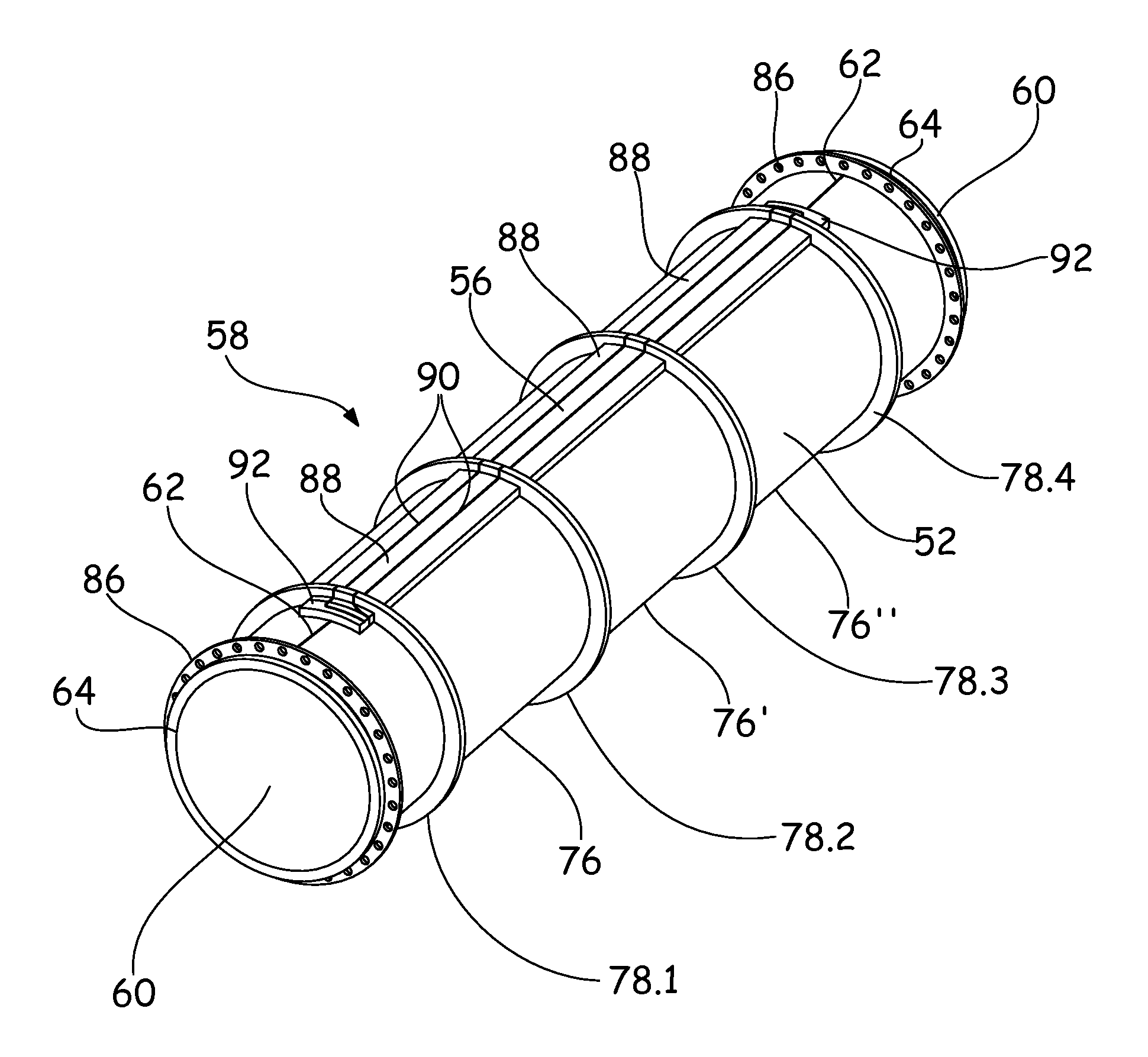
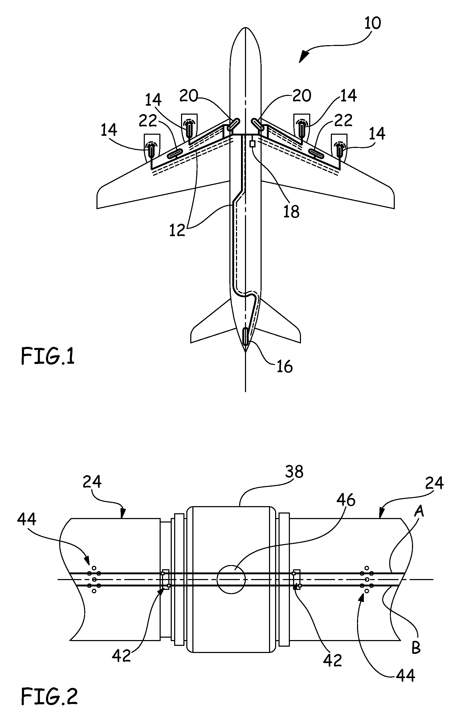
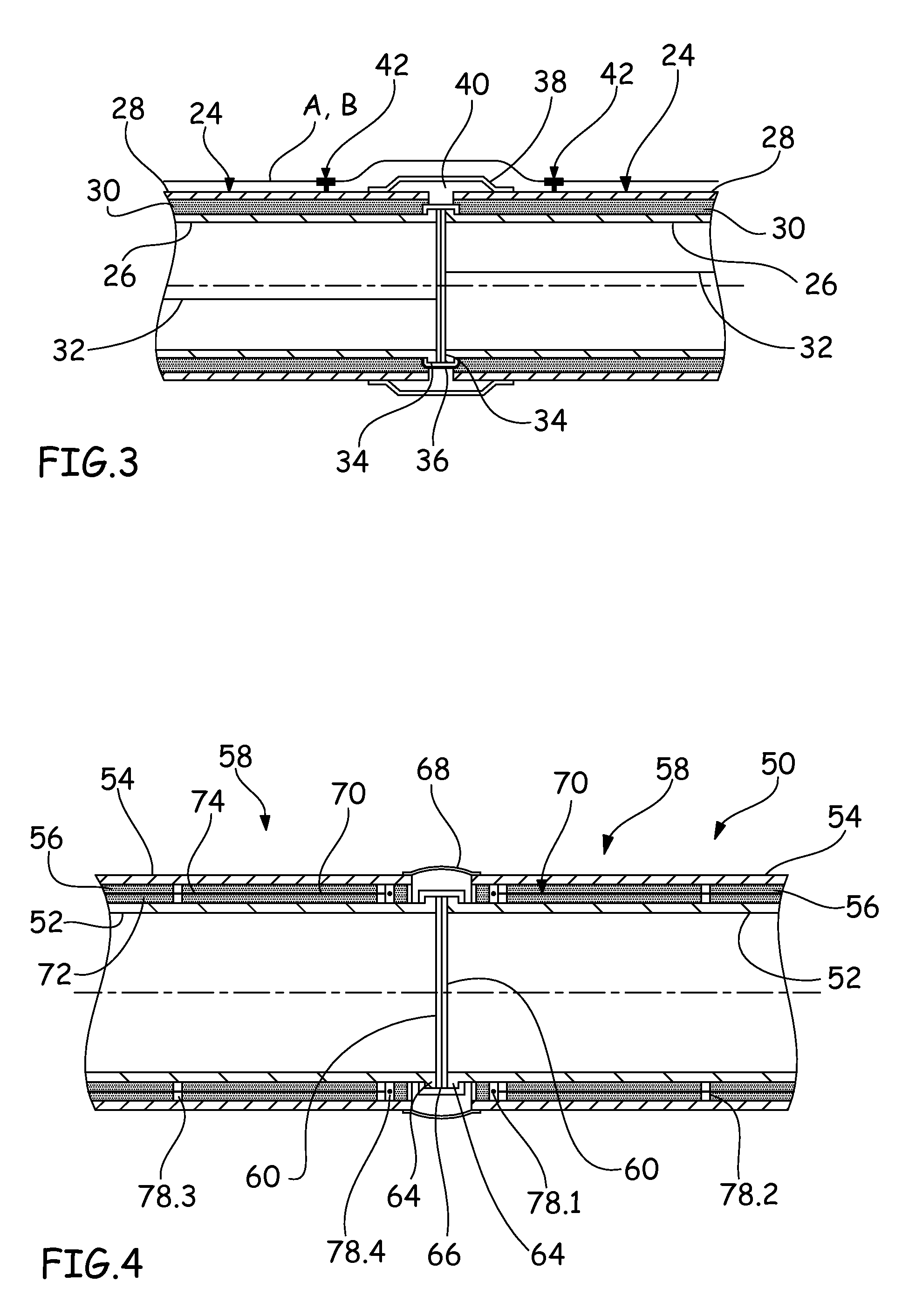
[0043]FIGS. 4, 5, 9 and 11 show a pipe 50 that makes it possible to channel the pressurized hot air into an aircraft. In a known manner, this pipe 50 comprises an inner tube 52, an outer tube 54 that is essentially coaxial to the inner tube 52, and insulating material 56 that is inserted between the two tubes 52 and 54. In general, the pipe 50 comprises several segments 58 that are placed end to end.

[0044]In all of the cases, a pipe or a segment 50 comprises at least one protruding end 60 that is connected to another pipe or another segment.

[0045]According to one embodiment, the inner tube 52 is obtained from at least one flat panel, made in particular of titanium, shaped and then welded on at least one generatrix 62 (visible in FIGS. 5 and 8).

[0046]The insulating material 56 can be based on glass wool. In all of the cases, it should be made of a heat-insulating and gas-porous material.

[0047]The outer tube 54, also called outer jacket, comes in the form of a sheet, made in particula...


PUM


Abstract

A pipe (50) that makes it possible to channel pressurized air into an aircraft, includes an inner tube (52), an outer tube (54) that is essentially coaxial to the inner tube (52), an insulating material (56) that is inserted between the two tubes (52, 54) and that is made of a heat-insulating and gas-porous material, and a leak detection device (70), characterized in that the leak detection device (70) is arranged at least in part between the inner tube (52) and the outer tube (54) and in that at least at one end (60), the detection device follows a concentric trajectory (84) to the inner tube (52).

Description

BACKGROUND OF THE INVENTION[0001]1. Field of the Invention[0002]This invention relates to a pressurized hot air pipe of an aircraft that is equipped with a leak detection device as well as a segment of said pipe.[0003]2. Description of the Related Art[0004]At 10, FIG. 1 shows an aircraft that integrates different sources of pressurized air that are connected, by a pipe network 12, to systems that have pressurized air requirements.[0005]The engines 14 as well as the auxiliary power group 16 constitute pressurized hot-air sources that are integrated into the aircraft. The latter can also comprise means 18 for connecting an externally pressurized air source, whereby said means 18 are located under the aircraft for supplying it with pressurized air when it is on the ground.[0006]As a system that uses pressurized air, the aircraft comprises, i.a., air-conditioning systems 20, wing-defrosting systems 22, ventilation systems, engine-starting systems, and the fuel-tank pressurization system...

Claims


Application Information

Patent Timeline
Patent Type & Authority Patents(United States)
IPC IPC(8): F16L55/00G01M3/04G01M3/00
CPCG01M3/045G01M3/002Y10T137/8158F16L59/143F16L55/07F16L2201/30
Inventor MILLET, GERARDBERNARD, XAVIERNOECKER, MATTHIAS
Owner AIRBUS OPERATIONS (SAS)
Why Eureka
Try Eureka