AI technical title is built by Patsnap AI team. It summarizes the technical point description of the patent document.
a linear accumulation and x-ray technology, applied in the direction of x-ray tubes, x-ray tube target materials, x-ray tube targets and convertors, etc., can solve the problems of large buildings and acres of land for their implementation, physical very large systems of synchrotron or fel systems, and the limit of improvement, so as to achieve high thermal conductivity and improve the efficiency of x-ray generating materials , the effect of high electron density
Active Publication Date: 2016-07-12
SIGRAY INC
View PDF131 Cites 51 Cited by
Summary
Abstract
Description
Claims
Application Information
AI Technical Summary
This helps you quickly interpret patents by identifying the three key elements:
Problems solved by technology
Method used
Benefits of technology
Benefits of technology
[0040]This disclosure presents novel x-ray sources that have the potential of being up to several orders of magnitude brighter than existing commercial x-ray technologies. The higher brightness is achieved in part through the use of novel configurations for x-ray targets used in generating x-rays from electron beam bombardment. The x-ray target configurations may comprise a number of microstructures of one or more selected x-ray generating materials fabricated in close thermal contact with (such as embedded in or buried in) a substrate with high thermal conductivity, such that the heat is more efficiently drawn out of the x-ray generating material. This in turn allows bombardment of the x-ray generating material with higher electron density and / or higher energy electrons, which leads to greater x-ray brightness.
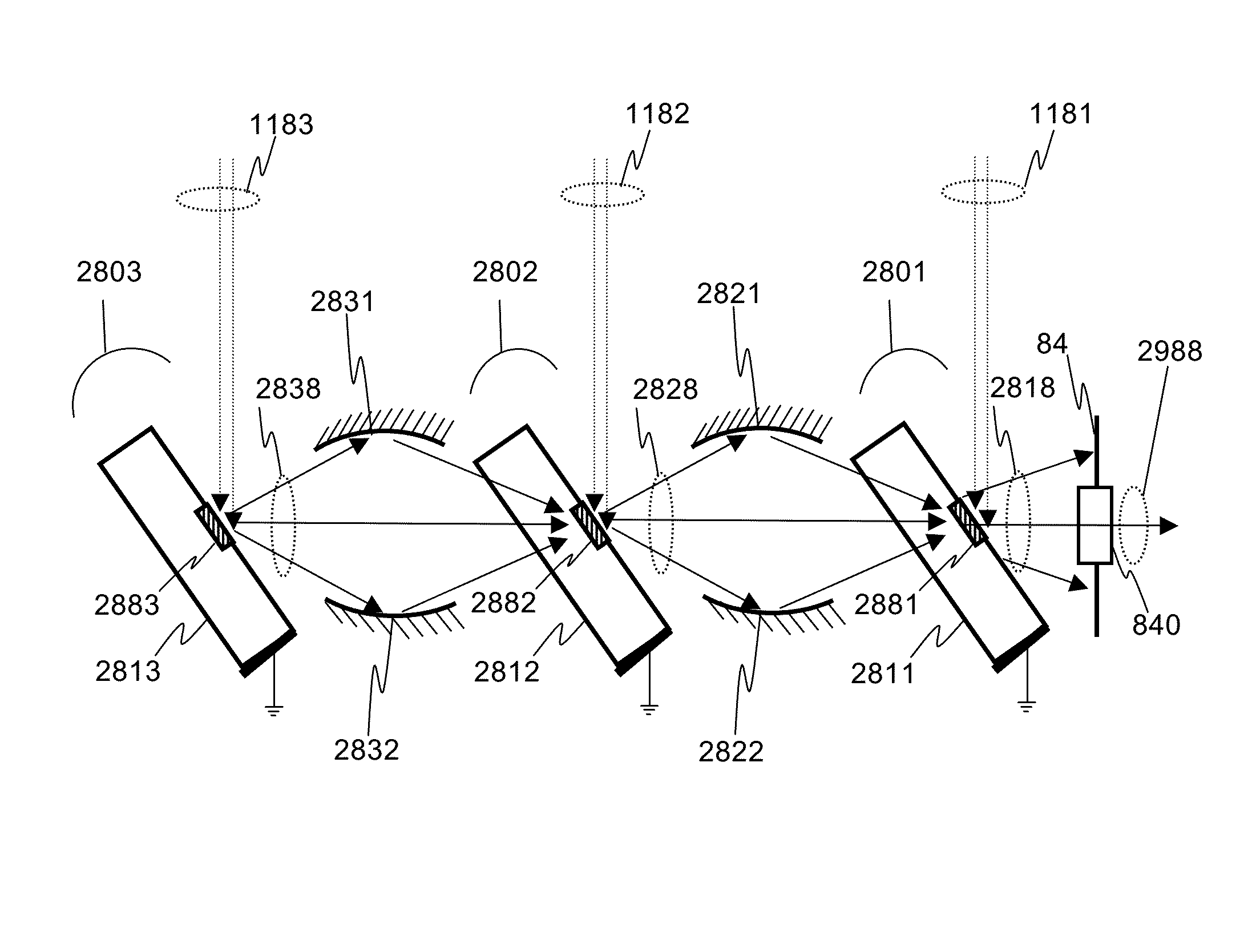
[0041]A significant advantage to some embodiments is that the orientation of the microstructures allows the use of an on-axis collection angle, allowing the accumulation of x-rays from several microstructures to be aligned to appear to originate at a single origin, and can be used for alignments at “zero-angle” x-ray radiation. The linear accumulation of x-rays from the multiple origins leads to greater x-ray brightness.
Problems solved by technology
These synchrotron or FEL systems, however, are physically very large systems, requiring large buildings and acres of land for their implementation.
However, with an extensive flat target, there is a limit to this benefit, due to the increasing absorption of x-rays from their production points inside the target as they propagate to the surface, which increases with a smaller take-off angle.
However, these improvements have a limit, in that all can increase the amount of heat generated in the interaction volume.
However, as noted in Table I, diamond is a very poor electrical conductor, so the design of any anode fabricated on a diamond substrate must still provide an electrical connection between the target material of the anode and the positive terminal of the high voltage.
Jets of liquid metal require an elaborate plumbing system and consumables, are limited in the materials (and thus values of Z and their associated spectra) that may be used, and are difficult to scale to larger output powers.
In the case of thin film targets of uniform solid material coated onto diamond substrates, there is still a limitation in the amount of heat that can be tolerated before damage to the film may occur, even if used in a rotating anode configuration.
In a lateral dimension, the same conduction problem exists as exists in the bulk material.
Method used
Image
Click on the blue label to locate the original text in one second.
Reading with bidirectional positioning of images and text.
Examples
Embodiment Construction
1. A Basic Embodiment of the Invention
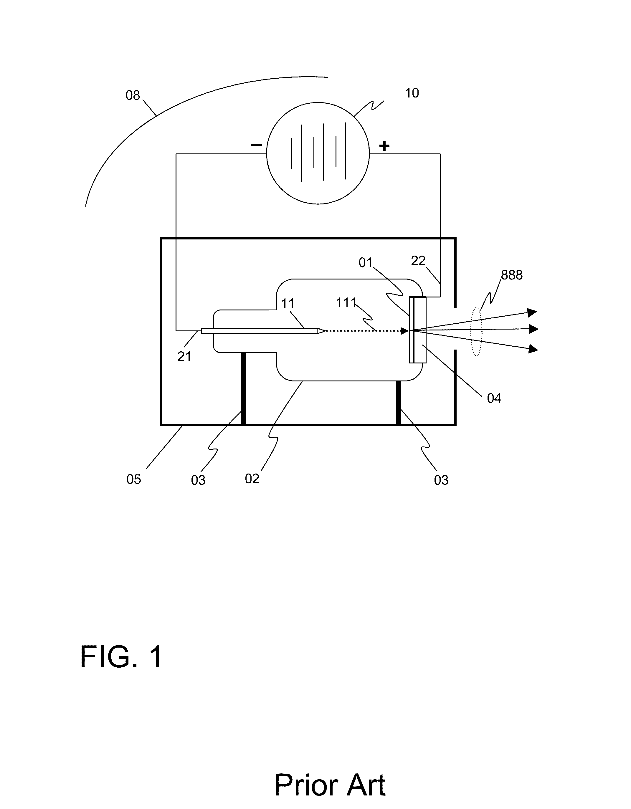
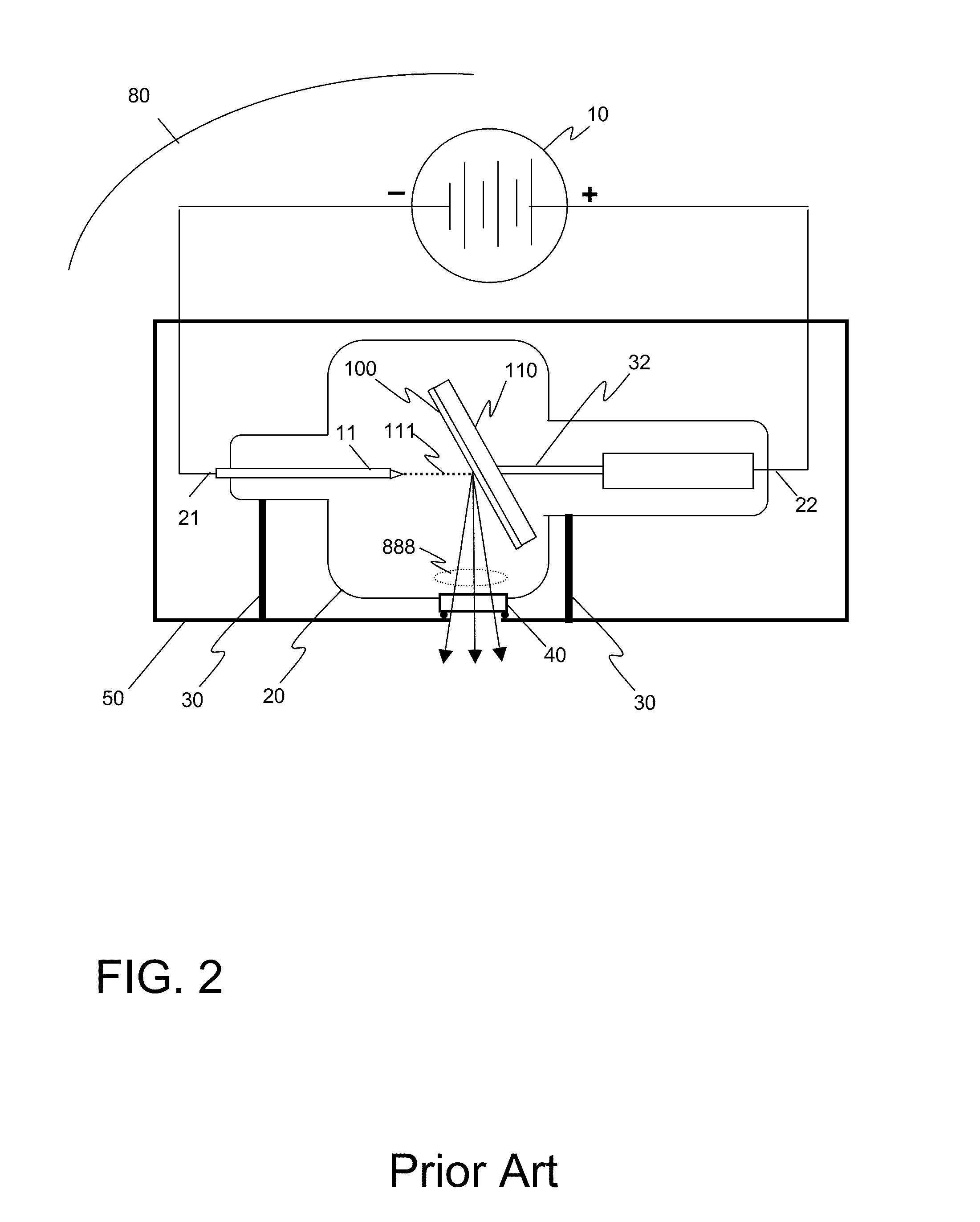
[0111]FIG. 7 illustrates an embodiment of a reflective x-ray system 80-A according to the invention. As in the prior art reflective x-ray system 80 described above, the source comprises a vacuum environment (typically 10−6 torr or better) commonly maintained by a sealed vacuum chamber 20 or active pumping, and manufactured with sealed electrical leads 21 and 22 that pass from the negative and positive terminals of a high voltage source 10 outside the tube to the various elements inside the vacuum chamber 20. The source 80-A will typically comprise mounts 30 which secure the vacuum chamber 20 in a housing 50, and the housing 50 may additionally comprise shielding material, such as lead, to prevent x-rays from being radiated by the source 80-A in unwanted directions.
[0112]As before, inside the chamber 20, an emitter 11 connected through the lead 21 to the negative terminal of a high voltage source 10 serves as a cathode and generates a beam of ele...
PUM
Abstract
A compact source for high brightness x-ray generation is disclosed. The higher brightness is achieved through electron beam bombardment of multiple regions aligned with each other to achieve a linear accumulation of x-rays. This may be achieved by aligning discrete x-ray sub-sources, or through the use of x-ray targets that comprise microstructures of x-ray generating materials fabricated in close thermal contact with a substrate with high thermal conductivity. This allows heat to be more efficiently drawn out of the x-ray generating material, and in turn allows bombardment of the x-ray generating material with higher electron density and / or higher energy electrons, leading to greater x-ray brightness.Some embodiments of the invention comprise x-ray optical elements placed between sub-sources of x-rays. These x-ray optical elements may form images of one or more x-ray sub-sources in alignment with other x-ray sub-sources, and may enhance the linear accumulation that can be achieved.
Description
CROSS-REFERENCE TO RELATED APPLICATIONS[0001]This Patent Application claims the benefit of U.S. Provisional Patent Application Nos. 61 / 880,151, filed on Sep. 19, 2013, 61 / 894,073, filed on Oct. 22, 2013, 61 / 931,519, filed on Jan. 24, 2014, and 62 / 008,856, filed on Jun. 6, 2014, all of which are incorporated herein by reference in their entirety.FIELD OF THE INVENTION[0002]The embodiments of the invention disclosed herein relate to high-brightness sources of x-rays. Such high brightness sources may be useful for a variety of applications in which x-rays are employed, including manufacturing inspection, metrology, crystallography, structure and composition analysis and medical imaging and diagnostic systems.BACKGROUND OF THE INVENTION[0003]The initial discovery of x-rays by Röntgen in 1895 [W. C. Röntgen, “Eine Neue Art von Strahlen (Würzburg Verlag, 1896); “On a New Kind of Rays,” Nature, Vol. 53, pp. 274-276 (Jan. 23, 1896)] occurred by accident when Röntgen was experimenting with e...
Claims
Application Information
Patent Timeline
Application Date:The date an application was filed.
Publication Date:The date a patent or application was officially published.
First Publication Date:The earliest publication date of a patent with the same application number.
Issue Date:Publication date of the patent grant document.
PCT Entry Date:The Entry date of PCT National Phase.
Estimated Expiry Date:The statutory expiry date of a patent right according to the Patent Law, and it is the longest term of protection that the patent right can achieve without the termination of the patent right due to other reasons(Term extension factor has been taken into account ).
Invalid Date:Actual expiry date is based on effective date or publication date of legal transaction data of invalid patent.

