Speed reduction mechanism, and motor torque transmission device including the speed reduction mechanism

a technology of speed reduction mechanism and transmission device, which is applied in the direction of electric propulsion mounting, transportation and packaging, gearing, etc., can solve the problems of increasing reducing the service life of each pin-side bearing, and not being economical to operate the motor torque transmission device described in jp 2007-218407 a. cost reduction and enhancement of the service life of bearings

Inactive Publication Date: 2016-07-19
JTEKT CORP
View PDF19 Cites 4 Cited by
  • Summary
  • Abstract
  • Description
  • Claims
  • Application Information

AI Technical Summary

Benefits of technology

[0013]It is an object of the invention to provide a speed reduction mechanism configured to contribute to cost reduction and enhancement of the service life of bearings, and a motor torque transmission device that includes the speed reduction mechanism.

Problems solved by technology

Therefore, employing the motor torque transmission device described in JP 2007-218407 A is not economical.
Accordingly, bearings having high durability need to be used as the pin-side bearings, resulting in cost increase.
In addition, if a load due to centrifugal force acts on the pin-side bearings, the service life of each pin-side bearing decreases.

Method used


Image

  • Speed reduction mechanism, and motor torque transmission device including the speed reduction mechanism
  • Speed reduction mechanism, and motor torque transmission device including the speed reduction mechanism
  • Speed reduction mechanism, and motor torque transmission device including the speed reduction mechanism

Examples


first embodiment

[0031]Hereinafter, a motor torque transmission device according to the invention will be described in detail with reference to the accompanying drawings.

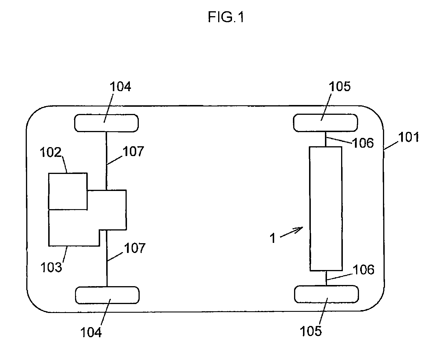
[0032]FIG. 1 schematically shows a four-wheel-drive vehicle 101. As shown in FIG. 1, the four-wheel-drive vehicle 101 has a front wheel power system and a rear wheel power system, and includes a motor torque transmission device 1, an engine 102, a transaxle 103, a pair of front wheels 104 and a pair of rear wheels 105. In the front wheel power system, the engine is used as a driving source. In the rear wheel power system, an electric motor is used as a driving source.

[0033]The motor torque transmission device 1 is arranged in the rear wheel power system of the four-wheel-drive vehicle 101, and is supported by a vehicle body (not shown) of the four-wheel-drive vehicle 101.

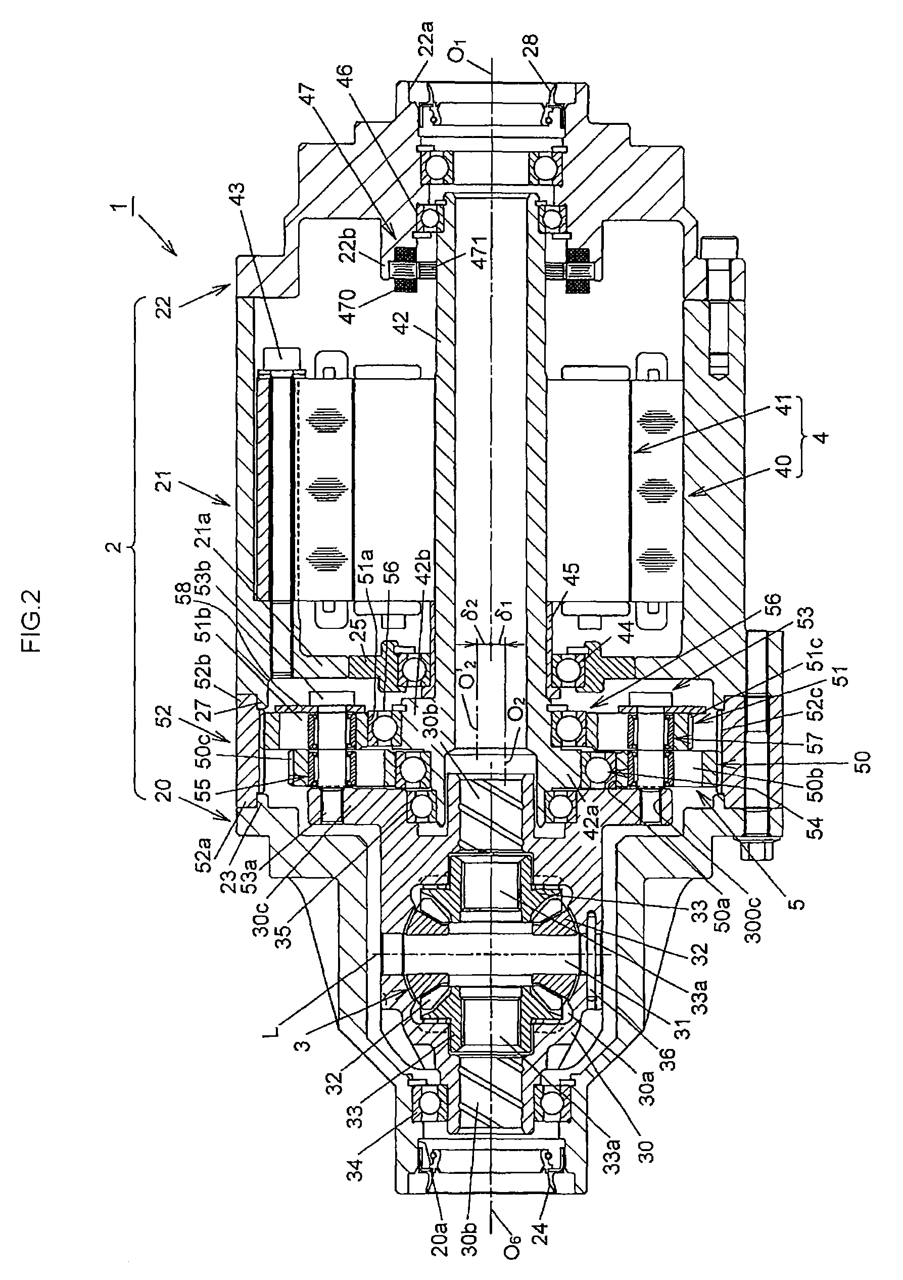
[0034]The motor torque transmission device 1 transmits driving force based on the motor torque of the electric motor 4 (shown in FIG. 2) to the rear wheels 105. Thu...

second embodiment

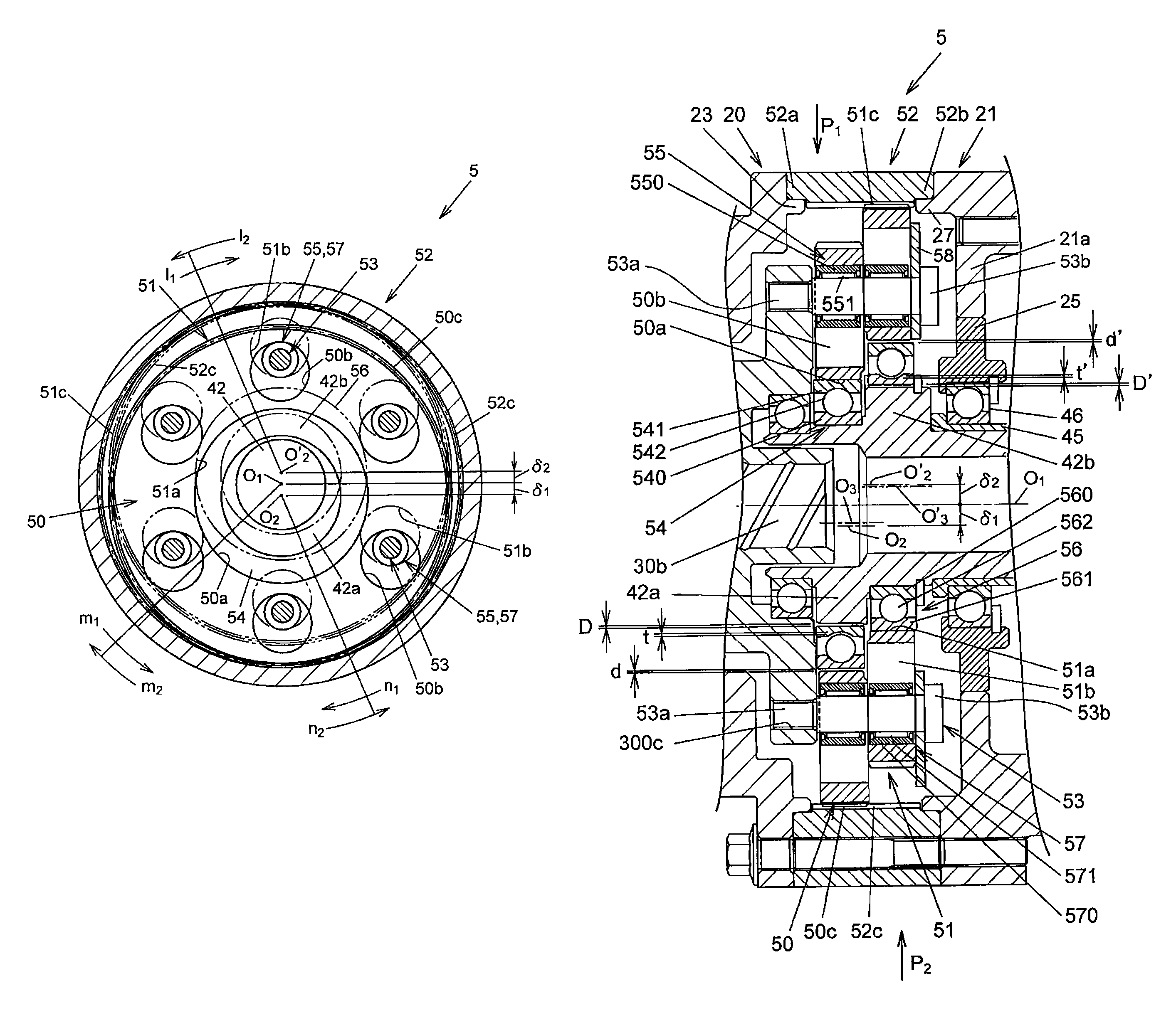
[0098]Next, a speed reduction mechanism in a motor torque transmission device according to the invention will be described with reference to FIG. 9. FIG. 9 shows a state where input members are supported and a state where second bearings are fitted. In FIG. 9, the members having the functions which are the same as or equivalent to those in FIG. 5 are denoted by the same reference numerals as those in FIG. 5, and the detailed description is omitted.

[0099]As shown in FIG. 9, a reduction-transmission mechanism 100 (partially shown) according to the second embodiment of the invention is characterized in that the inner rings 540, 560 of the ball bearings 54, 56 are fitted to the outer peripheries of the eccentric portions 42a, 42b by interference fit, and the outer rings 541, 561 are fitted to the inner peripheries of the input members 50, 51, which define the center holes 50a, 51a, by clearance fit.

[0100]Therefore, on the input member 50 side, if a size obtained by subtracting the outsi...

third embodiment

[0108]Next, a speed reduction mechanism in a motor torque transmission device according to the invention will be described with reference to FIG. 10. FIG. 10 shows a state where input members are supported and a state where second bearings are fitted. In FIG. 10, the members having the functions which are the same as or equivalent to those in FIG. 5 are denoted by the same reference numerals as those in FIG. 5, and the detailed description is omitted.

[0109]As shown in FIG. 10, a reduction-transmission mechanism 200 (partially shown) according to the third embodiment of the invention is characterized in that the inner rings 540, 560 of the ball bearings 54, 56 are fitted to the outer peripheries of the eccentric portions 42a, 42b by clearance fit, and the outer rings 541, 561 are fitted to the inner peripheries of the center holes 50a, 51 a by interference fit.

[0110]Therefore, on the input member 50 side, if a size obtained by subtracting the outside diameter of the eccentric portion...


PUM


Abstract

In a reduction-transmission mechanism, an input member is arranged at such a position that a size obtained by adding a fitting clearance formed between a ball bearing and an outer periphery of an eccentric portion, a fitting clearance formed between the ball bearing and an inner periphery of the input member, which defines a center hole, and a radial internal clearance of the ball bearing is smaller than a size obtained by adding a fitting clearance formed between an outer periphery of each of a plurality of output members and a corresponding one of needle roller bearings, a fitting clearance formed between each of the needle roller bearings and an inner periphery of the input member, which defines a corresponding one of a plurality of pin insertion holes, and a radial internal clearance of each of the needle roller bearings.

Description

INCORPORATION BY REFERENCE[0001]The disclosure of Japanese Patent Application No. 2012-074610 filed on Mar. 28, 2012 including the specification, drawings and abstract, is incorporated herein by reference in its entirety.BACKGROUND OF THE INVENTION[0002]1. Field of the Invention[0003]The invention relates to a speed reduction mechanism that is suitably used in, for example, an electric vehicle that has an electric motor as a driving source, and a motor torque transmission device that includes the speed reduction mechanism.[0004]2. Description of Related Art[0005]There is a conventional motor torque transmission device that is mounted on a vehicle, and that includes an electric motor and a reduction-transmission mechanism (see, for example, Japanese Patent Application Publication No. 2007-218407 (JP 2007-218407 A)). The electric motor generates motor torque. The reduction-transmission mechanism reduces the speed of rotation transmitted from the electric motor and then transmits drivi...

Claims


Application Information

Patent Timeline
Patent Type & Authority Patents(United States)
IPC IPC(8): H02K7/116F16H1/32B60K1/00
CPCH02K7/116F16H1/32B60K1/00F16H2001/325B60L15/2054B60L2240/421B60L2240/423B60L2240/486Y02T10/64Y02T10/72
Inventor TAKUNO, HIROSHISUZUKI, KUNIHIKOTAKAI, TOMOYOSHINOMURA, KEITAYAMAMORI, MOTOYASUKOBAYASHI, TSUNEONOZAKI, TOHRUTAGAMI, MASAHARU
Owner JTEKT CORP
Why Eureka
Try Eureka