Distortion compensation apparatus and distortion compensation method

a distortion compensation and distortion compensation technology, applied in the direction of rf amplifiers, amplifier modifications to reduce non-linear distortion, high frequency amplifiers, etc., can solve the problem of power leakage from a desired frequency band to an adjacent frequency band, radio communication quality deterioration, and difficulty in accurately estimating in advance a characteristic reverse to the nonlinear characteristic of a power amplifier

Inactive Publication Date: 2016-07-19
FUJITSU LTD
View PDF9 Cites 3 Cited by
  • Summary
  • Abstract
  • Description
  • Claims
  • Application Information

AI Technical Summary

Problems solved by technology

For example, however, nonlinear distortion of a transmitted signal due to the nonlinear amplification characteristic of a power amplifier may cause power leakage from a desired frequency band to an adjacent frequency band.
As a result, radio communication quality deteriorates.
However, it is not easy to correctly estimate in advance a characteristic reverse to the nonlinear characteristic of a power amplifier.
For example, a load at the time of compensation coefficient learning is heavy or the costs are high because of the use of high performance signal processing units.
However, if components in a part of frequency bands are simply removed in order to limit a bandwidth, distortion included in the part of the frequency bands is not taken into consideration.

Method used


Image

  • Distortion compensation apparatus and distortion compensation method
  • Distortion compensation apparatus and distortion compensation method
  • Distortion compensation apparatus and distortion compensation method

Examples


first embodiment

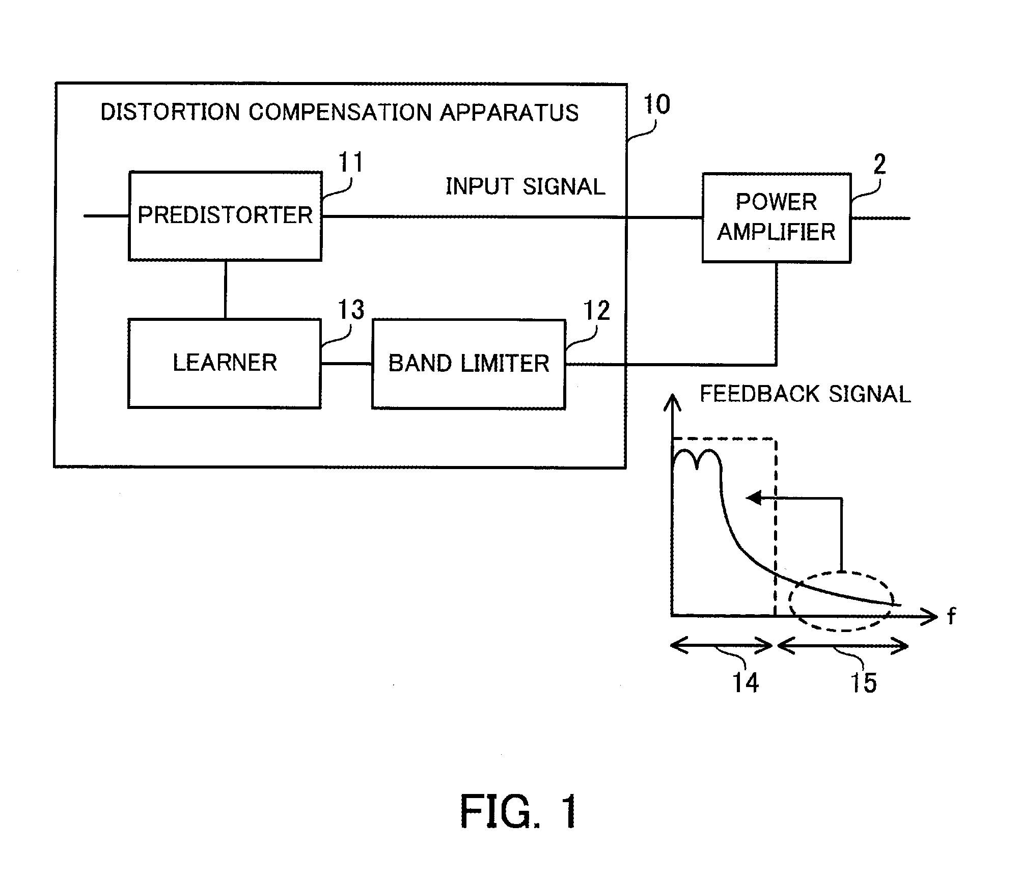
[0029]FIG. 1 illustrates an example of a distortion compensation apparatus according to a first embodiment.

[0030]A distortion compensation apparatus 10 according to a first embodiment compensates for nonlinear distortion caused by a power amplifier 2. This nonlinear distortion occurs in an output signal from the power amplifier 2 because there is a nonlinear relationship (amplification characteristic) between the level of an input signal to the power amplifier 2 and the level of an output signal from the power amplifier 2. The power amplifier 2 may be an amplifier referred to as an HPA (High Power Amplifier). The power amplifier 2 and the distortion compensation apparatus 10 are included in, for example, a radio transmitter which transmits a radio signal. The radio transmitter is a radio base station, a radio relay unit, a radio terminal unit, or the like.

[0031]The distortion compensation apparatus 10 includes a predistorter 11, a band limiter 12, and a learner 13.

[0032]The predisto...

second embodiment

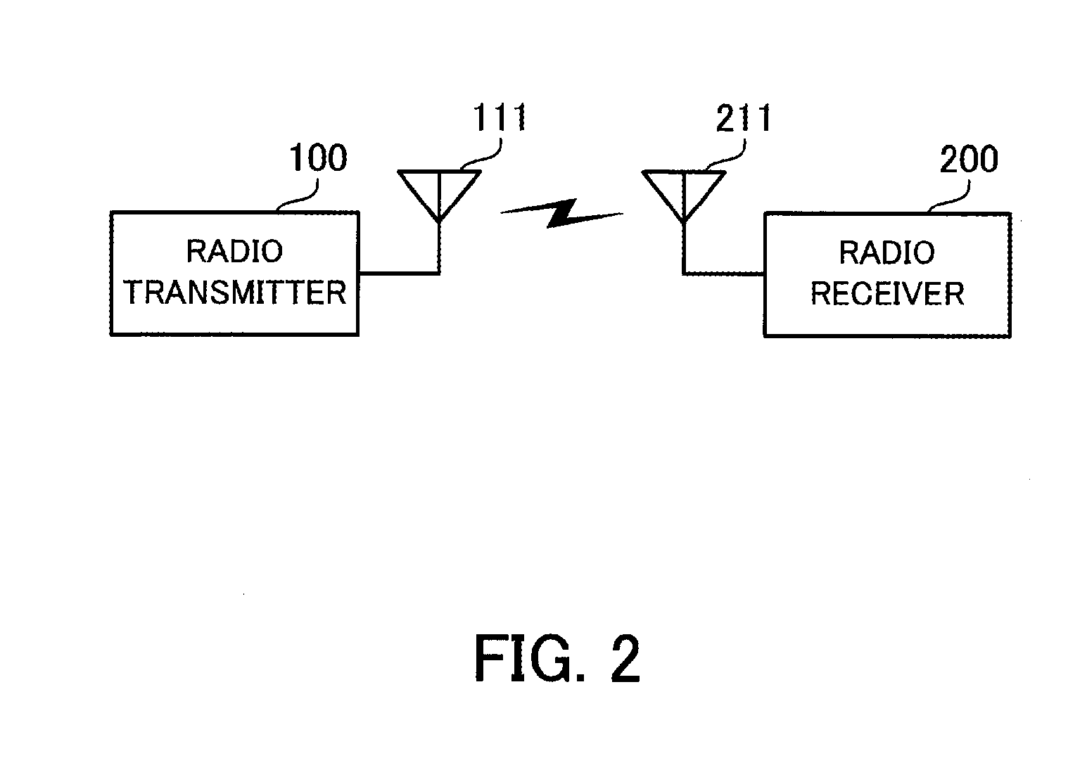
[0040]FIG. 2 illustrates an example of a radio communication system according to a second embodiment.

[0041]A radio communication system according to a second embodiment includes a radio transmitter 100 and a radio receiver 200. The radio transmitter 100 includes an antenna 111 and uses the antenna 111 for transmitting a radio signal to the radio receiver 200. The radio receiver 200 includes an antenna 211 and uses the antenna 211 for receiving a radio signal from the radio transmitter 100.

[0042]In the second embodiment a transmission process performed by the radio transmitter 100 will mainly be described. However, a radio communication apparatus corresponding to the radio transmitter 100 may further perform a receiving process or a radio communication apparatus corresponding to the radio receiver 200 may further perform a transmission process. Furthermore, this radio communication system may be a one-to-many connection system in which a radio base station communicates with a plurali...


PUM


Abstract

A predistorter gives an input signal inputted to a power amplifier distortion corresponding to a compensation coefficient. A band limiter limits components in a second frequency band other than a first frequency band of a feedback signal fed back from the power amplifier, and distorts components in the first frequency band according to the limited components in the second frequency band. A learner updates the compensation coefficient on the basis of the distorted feedback signal.

Description

CROSS-REFERENCE TO RELATED APPLICATION[0001]This application is based upon and claims the benefit of priority of the prior Japanese Patent Application No. 2014-015581, filed on Jan. 30, 2014, the entire contents of which are incorporated herein by reference.FIELD[0002]The embodiments discussed herein are related to a distortion compensation apparatus and a distortion compensation method.BACKGROUND[0003]A power amplifier for amplifying a transmitted signal is used in a radio transmitter which transmits a radio signal in a radio communication system. A power amplifier has a linear characteristic in a region in which the amplitude of an input signal is small. That is to say, there is an approximately linear relationship between the amplitude of an input signal and the amplitude of an output signal. On the other hand, a power amplifier has a nonlinear characteristic in a region in which the amplitude of an input signal is large. That is to say, there is a nonlinear relationship between ...

Claims


Application Information

Patent Timeline
Patent Type & Authority Patents(United States)
IPC IPC(8): H03F1/26H03F3/19H03F1/32H03F3/24
CPCH03F1/3258H03F3/19H03F3/245H03F1/3247H03F2200/102H03F2200/451H03F2201/3227
Inventor LOZHKIN, ALEXANDER NIKOLAEVICH
Owner FUJITSU LTD
Why Eureka
Try Eureka