
Shadow casting alignment technique for seamless displays

a technology of seamless display and shadow casting, applied in the field of optical displays, can solve the problems of reducing the yield of large displays, causing an exponential increase in costs, and prohibitively expensive large wall displays

Inactive Publication Date: 2016-07-26
X DEV LLC
View PDF21 Cites 2 Cited by
  • Summary
  • Abstract
  • Description
  • Claims
  • Application Information

AI Technical Summary

Benefits of technology

The system achieves a high-quality, seamless multi-tile display by minimizing visible seams and reducing manufacturing costs, providing a visually imperceptible transition between image portions from a typical viewing distance.

Problems solved by technology

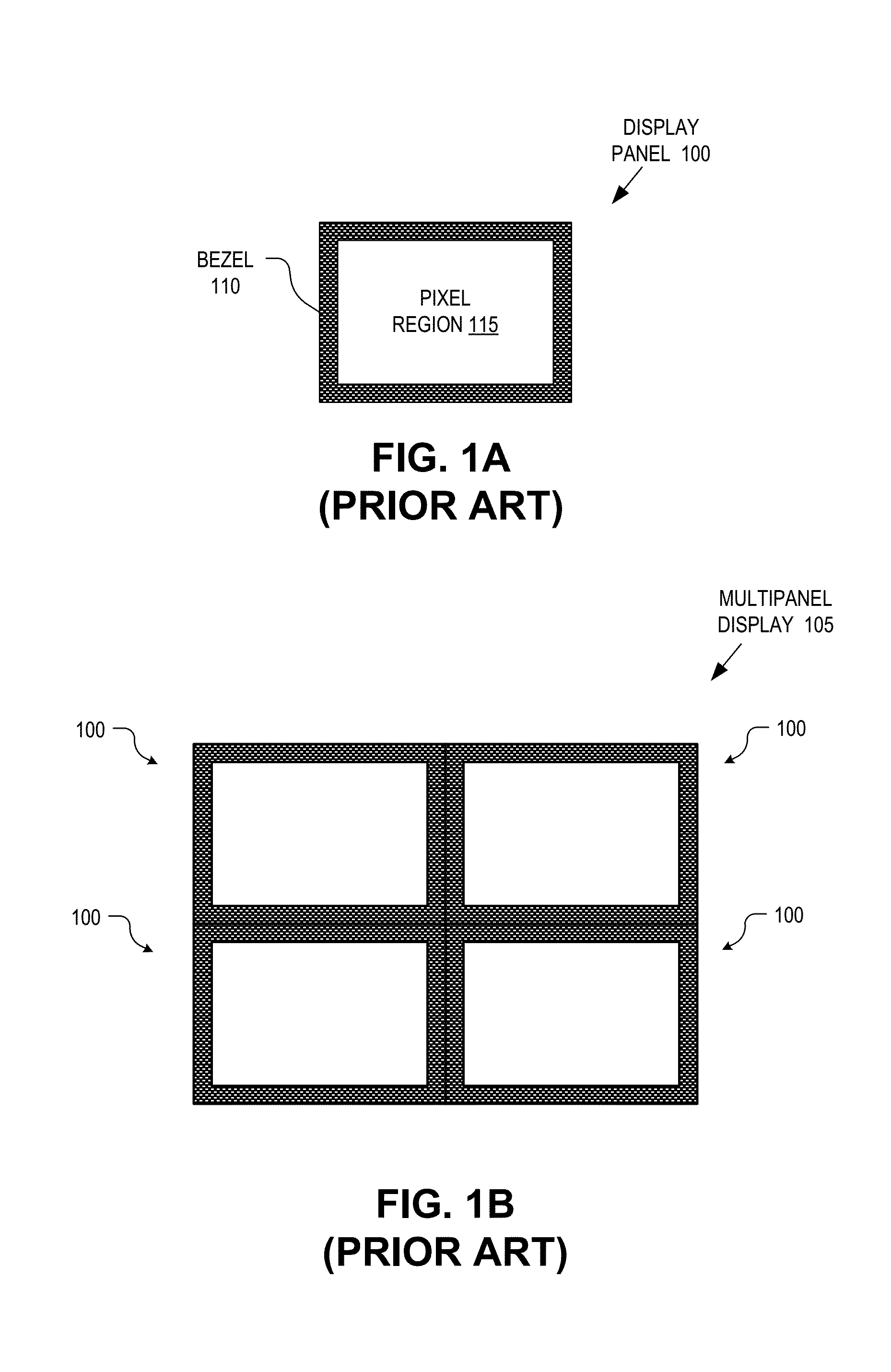
Large wall displays can be prohibitively expensive as the cost to manufacture display panels rises exponentially with monolithic display area.
This exponential rise in cost arises from the increased complexity of large monolithic displays, the decrease in yields associated with large displays (a greater number of components must be defect free for large displays), and increased shipping, delivery, and setup costs.
While multi-panel display 105 can reduce costs, visually it has a major drawback.
However, even these thin bezel trims are still very noticeable to the naked eye, distract the viewer, and otherwise detract from the overall visual experience.

Method used


Image

  • Shadow casting alignment technique for seamless displays
  • Shadow casting alignment technique for seamless displays
  • Shadow casting alignment technique for seamless displays

Examples


Embodiment Construction

[0015]Embodiments of a system, apparatus, and method for aligning optical layers of a multi-layer display are described herein. In the following description numerous specific details are set forth to provide a thorough understanding of the embodiments. One skilled in the relevant art will recognize, however, that the techniques described herein can be practiced without one or more of the specific details, or with other methods, components, materials, etc. In other instances, well-known structures, materials, or operations are not shown or described in detail to avoid obscuring certain aspects.

[0016]Reference throughout this specification to “one embodiment” or “an embodiment” means that a particular feature, structure, or characteristic described in connection with the embodiment is included in at least one embodiment of the present invention. Thus, the appearances of the phrases “in one embodiment” or “in an embodiment” in various places throughout this specification are not necess...


PUM

PropertyMeasurementUnit
thicknessaaaaaaaaaa
fixed distanceaaaaaaaaaa
widthaaaaaaaaaa

Abstract

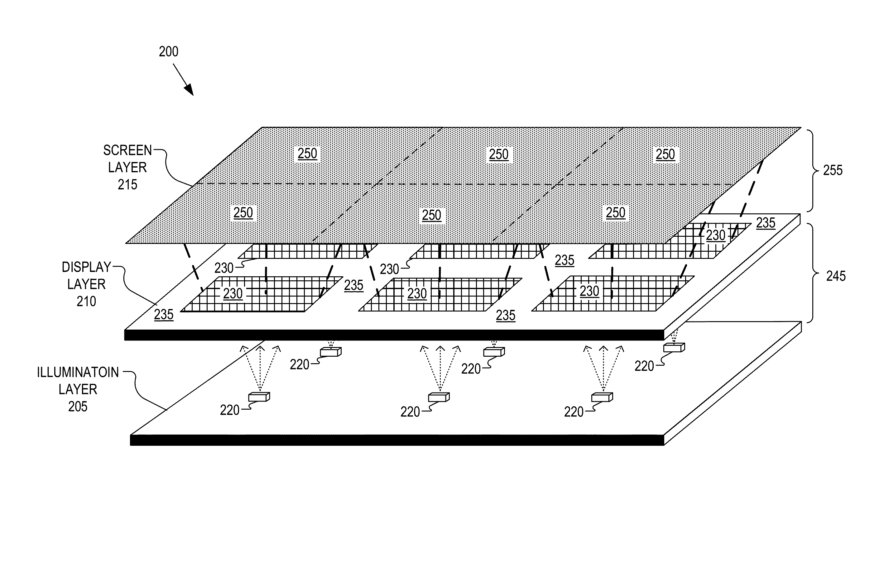
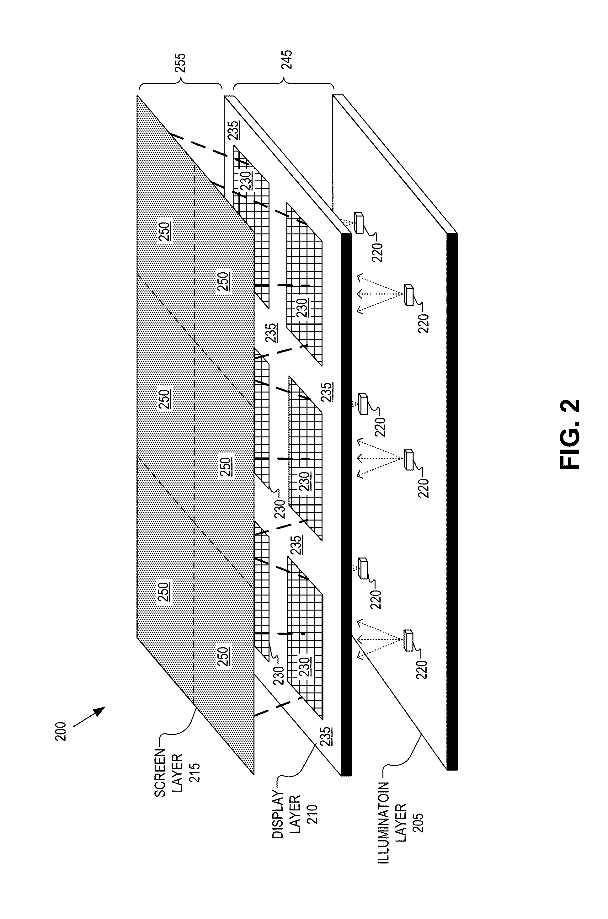
A method for aligning optical layers of a multi-layer display includes displaying a dark screen image on each of a plurality of transmissive pixel arrays separated from each other by spacing regions. The transmissive pixel arrays are disposed on a display layer of the multi-layer display. The display layer is illuminated with a plurality of illumination sources of an illumination layer disposed behind the display layer. Each of the illumination sources corresponds to one of the transmissive pixel arrays to illuminate the corresponding one of the transmissive pixel arrays. An illumination pattern is cast onto a screen layer disposed in front of the display layer. The illumination pattern includes bright regions due to overlapping illumination cast from adjacent ones of the transmissive pixel arrays. The bright regions of the illumination pattern cast onto the screen layer are analyzed to identify misalignments between the display layer and the illumination layer.

Description

TECHNICAL FIELD[0001]This disclosure relates generally to optical displays, and in particular but not exclusively, relates to seamless tiling of optical displays.BACKGROUND INFORMATION[0002]Large wall displays can be prohibitively expensive as the cost to manufacture display panels rises exponentially with monolithic display area. This exponential rise in cost arises from the increased complexity of large monolithic displays, the decrease in yields associated with large displays (a greater number of components must be defect free for large displays), and increased shipping, delivery, and setup costs. Tiling smaller display panels to form larger multi-panel displays can help reduce many of the costs associated with large monolithic displays.[0003]FIGS. 1A and 1B illustrate how tiling multiple smaller, less expensive display panels 100 together can achieve a large multi-panel display 105, which may be used as a large wall display. The individual images displayed by each display panel ...

Claims


Application Information

Patent Timeline
Patent Type & Authority Patents(United States)
IPC IPC(8): G02F1/1333G01B11/14G01B11/27G02F1/13
CPCG02F1/13336G01B11/14G01B11/272G02F1/1309G02F2001/133354G09G2320/0693G02F1/133354
Inventor BASTANI, BEHNAMMILANFAR, PEYMAN
Owner X DEV LLC
Learn More