Smart electrical switch with audio capability

a technology of electrical switches and audio speakers, which is applied in the direction of electrical transducers, transducer casings/cabinets/supports, and sustainable buildings. it can solve the problems of reducing the functionality of the junction box by 1 switch, and reducing the functionality of the junction box. it achieves full electrical switch functionality, improves sound quality, and maintains sound quality.

Inactive Publication Date: 2016-08-02
LIVESPACE INC
View PDF14 Cites 7 Cited by
  • Summary
  • Abstract
  • Description
  • Claims
  • Application Information

AI Technical Summary

Benefits of technology

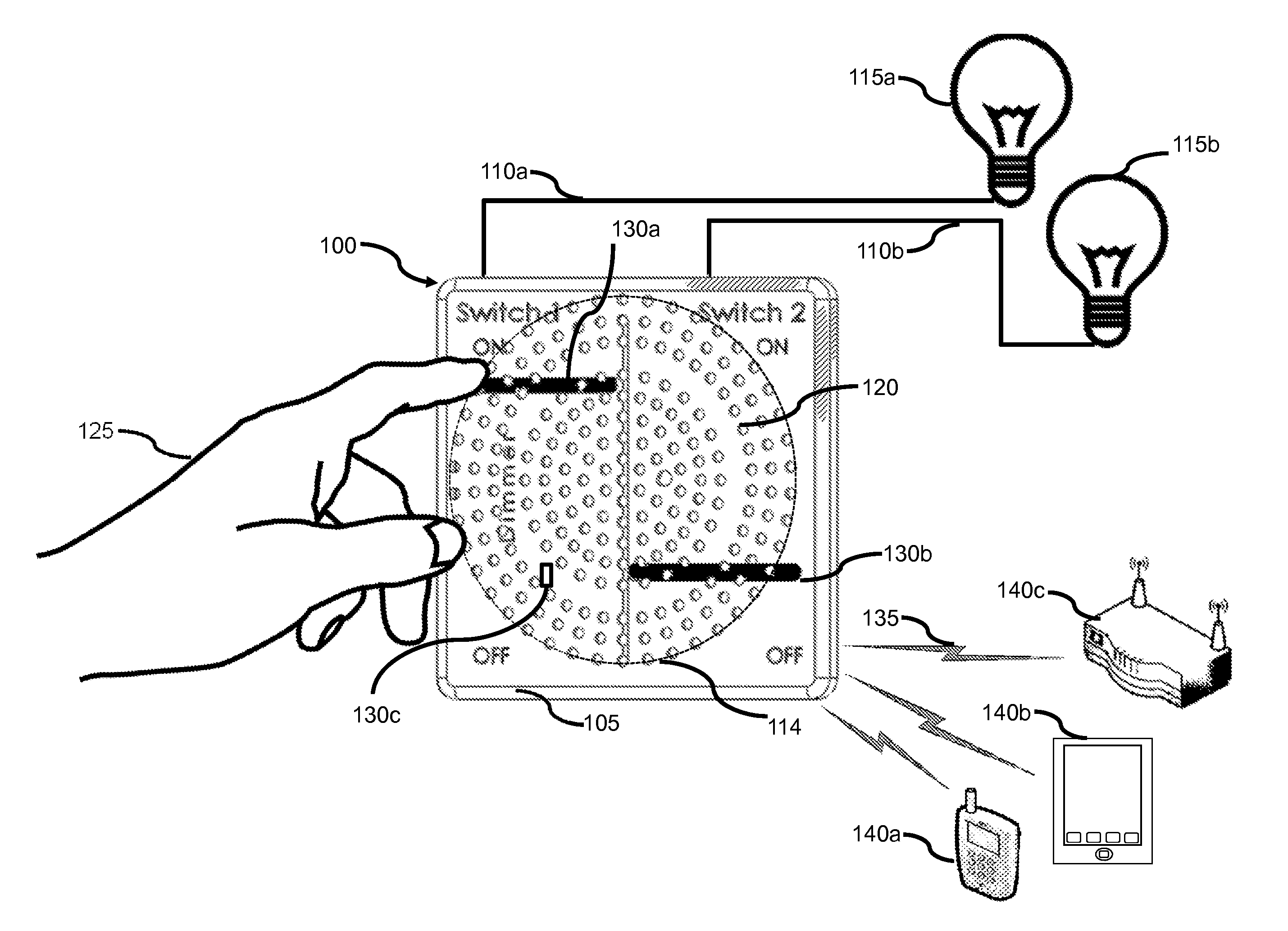
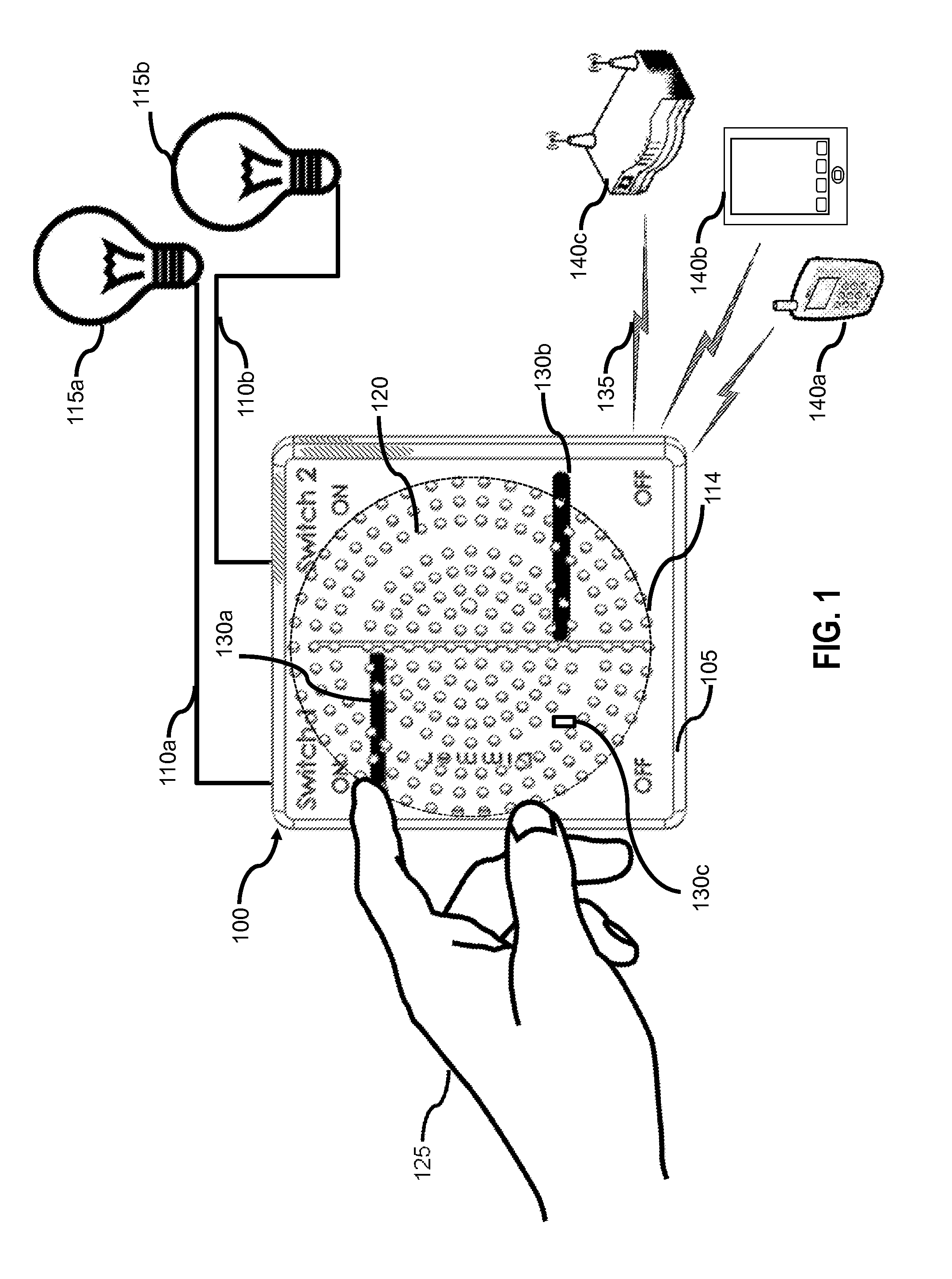
[0010]In one embodiment a building-based electrical switch assembly (e.g. a light switch) in a wall-mounted junction box includes a speaker and an interactive speaker grille. The speaker grille has a several distinct touch-sensitive regions and fulfills the legacy functionality of one or more electrical switches. The design enables a bigger speaker to be centrally located in the junction box, for enhanced music quality, while maintaining all of the functionality of the electrical switch. The faceplate can be located similarly to a traditional light switch faceplate. The faceplate covers the transition from the wall to the junction box. The faceplate of the present system can also have a plurality of openings forming a speaker grille for the speaker. The openings extend over the center region of the faceplate to provide protection for the speaker cone behind, while allowing sound vibrations to be emitted from the speaker.
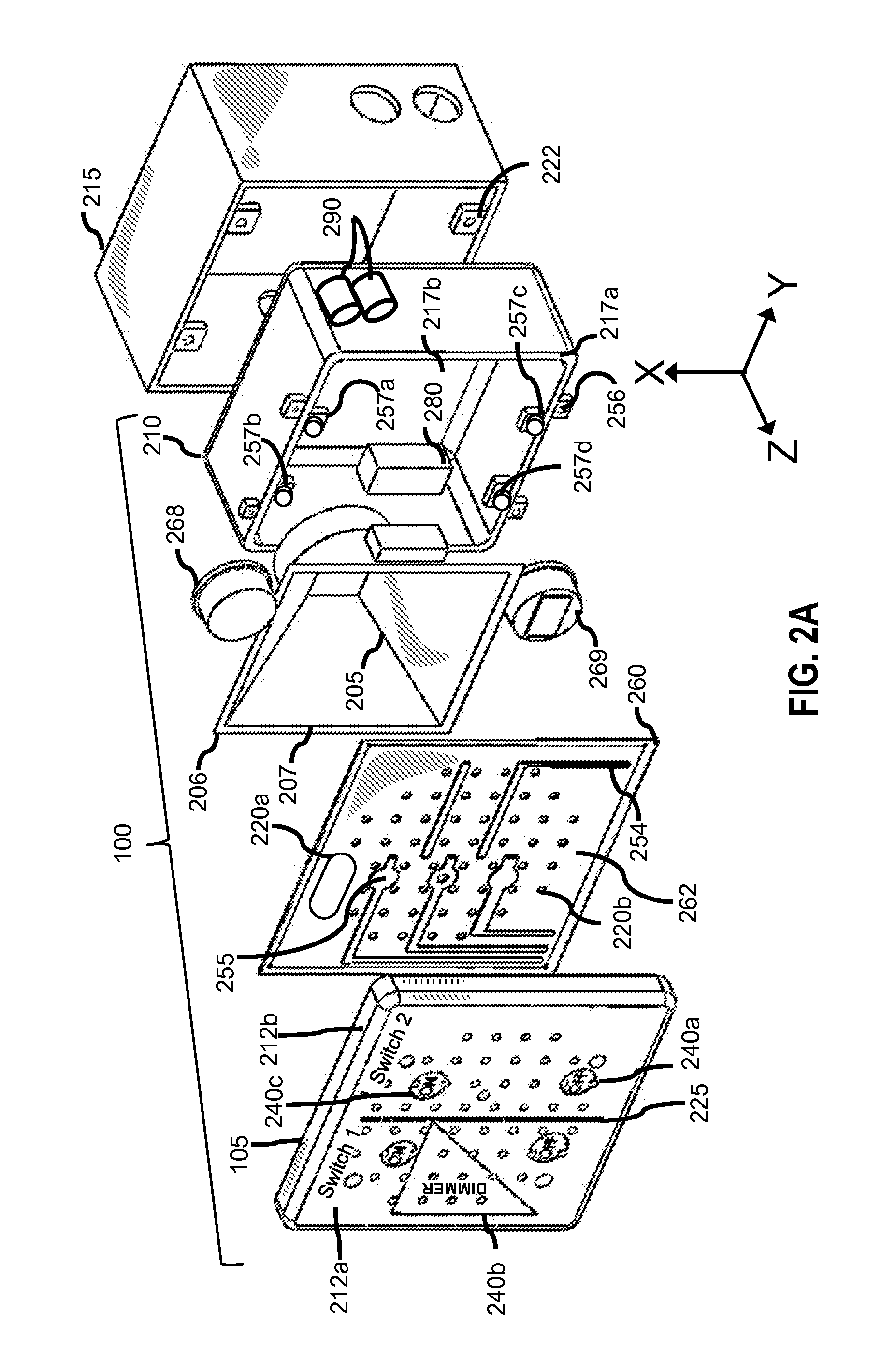
[0012]In one aspect of the disclosure, the grille section of the faceplate has a plurality of touch-sensitive regions enabled by touch sensors behind the front insulating faceplate. One or more of the touch sensors can also provide control over aspects of the speaker. In another aspect of the disclosure touch sensitive electrodes can be disposed on a substrate behind the grille, wherein the substrate has a plurality of opening that align with the grille, thereby providing touch sensitive functionality to the grille while maintaining the sound quality from the speaker and providing electrical insulation.
[0013]The disclosed designs enable the faceplate to act as both a grille for the speaker and as one or more electrical switches and thereby allows for a larger speaker to be placed centrally in the junction box, while maintaining full electrical switch functionality. This in turn allows the user to control the electrical switches and experience improved sound quality. In other embodiments illumination components are arranged on a circuit board with a plurality of openings aligning with the grille. The illumination components (e.g. electroluminescent regions) can light regions of the faceplate, indicating the current state of one or more electrical switches ((e.g. ON / OFF or degree of dimming). In this manner the speaker grille can act as an interactive control panel while not diminishing sound quality.
[0014]In some embodiments the speaker grille enables the system to detect when a person is proximal to the switch and activate an aspect of the speaker or switch. In one embodiment the speaker grille is an insulating material with conductive features deposited on the interior surface to enable person detection. In other embodiments elements deposited on the interior surface of the faceplate enable indication of the state of the switch. The techniques described in this specification can be implemented to achieve the following exemplary advantages:
[0015]Improved sound quality from an electrical switch by centrally locating a speaker where the switch typically resides. The system can be retrofitted in a building-based electrical junction box that is fully utilized without loss of any of the electrical load switching functionality. For example, previously a 2-bay junction box could accommodate a 2-inch wide speaker and a single 2-inch wide switch, thereby diminishing the functionality of the junction box by one switch while only allowing allow the speaker to occupy half of the junction box. With the present system both bays (4 inch by 4 inch) can be devoted to the speaker and the electrical switches can be implemented using the touch-sensitive speaker grille. The speaker can provide audio feedback when the switch is actuated, thereby providing the user with a familiar “click” sound associated with actuating a mechanical switch. The electrical switch with audio functionality can function as a wireless speaker for example a Bluetooth speaker offered to a hotel guest, while the location of the speaker is ensured by the placement of the speaker in the wall and power is supplied continuously from the electrical junction box.
[0016]A plurality of regions of the grille can illuminate in response to a user touching the faceplate and grille portion and can guide the user to correctly operate the switch or to indicate the current position of a switch or dimmer switch. Still further advantages will become apparent from a study of the following description and the accompanying drawings.

Problems solved by technology

Providing adequate music-quality sound in a small enclosure is difficult, in part because speakers typically requires a large volume of space in a device enclosure.
This practice of “right-sizing” junction boxes is in part because unused bays must be covered for safety purposes and the presence of nonfunctioning extra bays with blank cover plates can be confusing to users.
The practice of selecting the size of junction boxes to fit the original electrical requirements (e.g. lighting requirements and the need for switch-activated electrical outlets) is problematic to the task of adding additional functionality within junction boxes in existing homes.
An ongoing challenge is how to increase the functionality within household electrical boxes while maintain the original functionality, which is often to provide electrical switching (e.g. light switches).
One disadvantages of this approach is that it reduces the functionality of the junction box by 1 switch.
Another disadvantage is that this speaker-switch combination cannot be implemented in a single-bay junction box.
This is an important limitation since the light switch in many rooms is located in a single-bay junction box.
Importantly U.S. Pat. No. 7,608,948, U.S. Pat. No. 5,914,826 and U.S. Pat. No. 6,091,037 do not provide means to effectively combine the functions of sound transmission and electrical switching.
Similarly, no electrical switch assembly has combined both a speaker and a lighting switch in a single-bay configuration.
Similarly, no electrical switch assembly has provided a faceplate that effectively combines sound transmission and electrical switching.

Method used


Image

  • Smart electrical switch with audio capability
  • Smart electrical switch with audio capability
  • Smart electrical switch with audio capability

Examples


Embodiment Construction

FIG. 1-FIG. 11

[0032]In the following detailed description, for purposes of explanation, numerous specific details are set forth to provide a thorough understanding of the various implementations of the present invention. Those of ordinary skill in the art will realize that these various implementations of the present invention are illustrative only and are not intended to be limiting in any way. Other implementations of the present invention will readily suggest themselves to such skilled persons having the benefit of this disclosure.

[0033]In addition, for clarity purposes, not all of the routine features of the implementations described herein are shown or described. One of ordinary skill in the art would readily appreciate that in the development of any such actual implementation, numerous implementation-specific decisions may be required to achieve specific design objectives. These design objectives will vary from one implementation to another and from one developer to another. M...


PUM


Abstract

In one embodiment the present disclosure relates to providing wireless speaker functionality in an electrical switch assembly, such as a light switch located in the wall of a building. The switch assembly includes a faceplate with a touch-sensitive speaker grille covering a sizeable portion of the faceplate. The disclosed designs enables the grille portion of the faceplate to provide sound transmission and electrical switch control, thereby allows for a larger speaker to be placed centrally in the junction box, while maintaining full electrical switch functionality. In some embodiments illumination components (e.g. electroluminescent regions) are arranged on a circuit board with a plurality of openings designed to align with the grille. The illumination components can illuminate regions of the faceplate, indicating the current state of one or more electrical switches.

Description

CROSS-REFERENCE TO RELATED APPLICATIONS[0001]This application claims the benefit of patent application Ser. No. 14 / 788,726, filed on Jun. 30, 2015 by the present inventor.[0002]This application claims the benefit of provisional patent application Ser. No. 62 / 054,389, filed on Sep. 24, 2014 by the present inventor.REFERENCES[0003]The following is a tabulation of some prior art that presently appears relevant:U.S. Patents[0004]Patent NumberKind CodeIssue DatePatentee5,914,826A1999 Jun. 22Smallwood6,091,037A2000 Jul. 18Bachschmid3,927,402A1975 Dec. 16Thompson8,675,887B22014 Mar. 18Yuan et al.8,666,104B22014 Mar. 4Ivey et al.7,608,948B22009 Oct. 27Nearhoof et al.7,299,892B22007 Nov. 27Radu et al.U.S. Patent Application Publications[0005]Publication Nr.Kind CodePubl. DateApplicant20050237218A12005 Oct. 27Tang et al.20140270237A12014 Sep. 18Wang et al20140270264A12014 Sep. 18Wang et. al20110181201A12011 Jul. 28Hollis20070289860A12007 Dec. 20Newman et al.20060161270A12006 Jul. 20Luskin et ...

Claims


Application Information

Patent Timeline
Patent Type & Authority Patents(United States)
IPC IPC(8): H04R27/00H04R1/02H04W4/20H04W4/02H01H9/02H04W4/21
CPCH04R27/00H04R1/028H04W4/206H01H9/0271H04W4/023H04R1/023H01H9/02H04R2420/07H01H2239/048Y04S20/14H01H2300/03H04W4/21Y02B90/20
Inventor O'KEEFFE, JAMES THOMAS
Owner LIVESPACE INC
Why Eureka
Try Eureka