Contact focusing hollow-core fiber microprobes

a hollow-core fiber and micro-probe technology, applied in the field of optics and medical fields, can solve the problems of reduced optical beam quality, increased optical loss, and limited number, and achieve the effect of high optical throughput and flexible and efficient delivery

Active Publication Date: 2016-08-09
JUNIVERSITI OF NORT KAROLINA EHT SHARLOTT
View PDF11 Cites 1 Cited by
  • Summary
  • Abstract
  • Description
  • Claims
  • Application Information

AI Technical Summary

Benefits of technology

[0011]In various exemplary embodiments, the present invention provides systems and methods for the flexible optical delivery to and focusing of electromagnetic (i.e. laser) radiation at the surface of a sample, specimen, tissue, etc. The focusing microprobes utilize a single-mode or multi-mode laser source, a hollow-core fiber delivery system, and a focusing tip. The hollow-core fiber provides for flexible and efficient delivery of the single-mode or multi-mode laser radiation to the focusing tip. The focusing tip includes a lens, such as a (dielectric) microsphere or several (dielectric) microspheres assembled in a linear chain. The tip focuses the laser radiation down to diffraction limited beam diameters in a contact mode or near-contact mode, thereby providing high optical throughput and satisfying the requirements associated with ultraprecise laser surgery, micro-welding, bonding, surface patterning, and the like.

Problems solved by technology

The use of flexible optical delivery systems typically leads to additional optical losses and to reduced quality of the optical beams.
There are many factors contributing to optical losses in such systems, including coupling losses between a source and the flexible optical delivery system, coupling losses in a focusing tip, absorption, scattering and reflection, and other factors.
Third, for focusing microprobes, the diameter of the focused laser beam at the tip of the microprobe must be minimized in order to provide more localized laser action. In the case of ultraprecise laser surgery, for example, this is required to minimize the size of ablation craters in the tissue.
Fourth, in many applications, the microprobe must be able to operate in contact or in near contact with the tissue or other specimen. In some applications, this is required due to strong absorption of the laser radiation by the surrounding medium. It can also make the surgery or other procedure easier and more efficient to perform.
As a result, a few modes are guided by the system, however, this number is very limited, typically in 2-6 range.
However, such fibers are not well developed for the mid-IR ranges of wavelengths required for some applications, such as a contact laser surgery.

Method used


Image

  • Contact focusing hollow-core fiber microprobes
  • Contact focusing hollow-core fiber microprobes
  • Contact focusing hollow-core fiber microprobes

Examples


Embodiment Construction

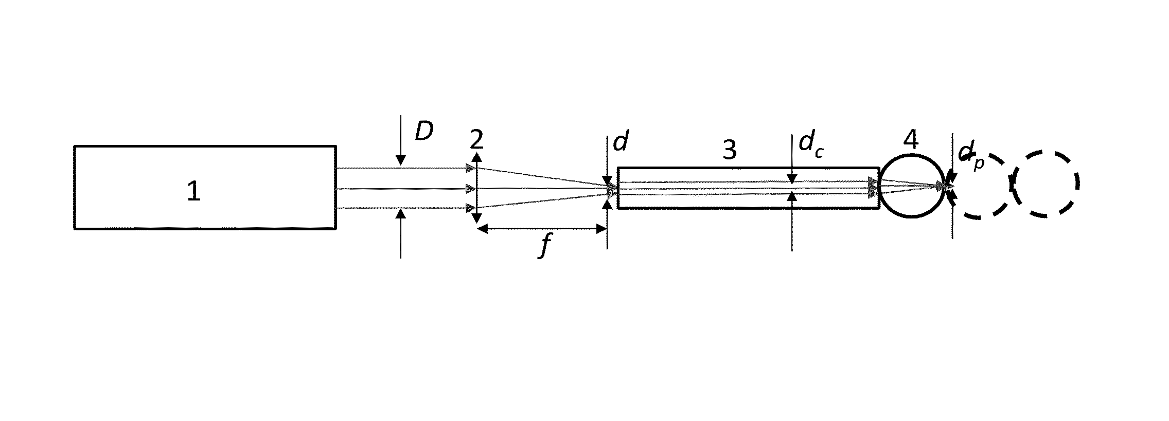
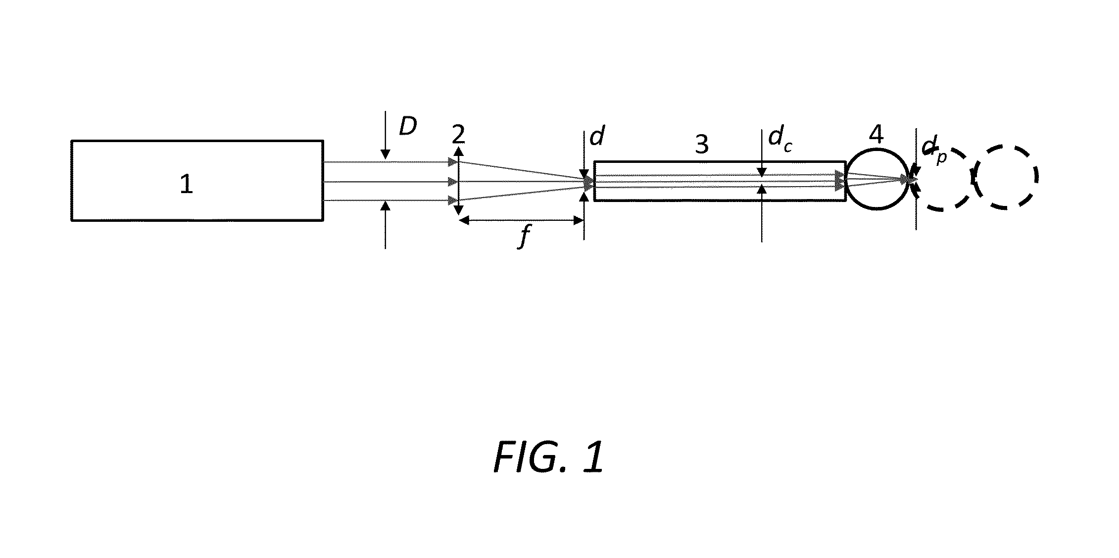
[0018]Referring now specifically to FIG. 1, in one exemplary embodiment, the focusing microprobe of the present invention includes a laser radiation source (1), a focusing lens (2), a flexible optical delivery system (3), and one or more microlenses (4) assembled as a focusing tip. For efficient coupling of the source to the delivery system, two main conditions must be satisfied. First, the diameter, d, of the focused laser beam at the edge of the delivery system (either fiber or waveguide) must be smaller than the diameter of the core, dc, of the delivery system. The focused beam diameter can be approximated by the formula:

d=M2λ / (2NAi),

where M2 is a laser beam quality number indicating how close the laser beam is to being a single-mode beam and NAi=nsinθi≈nD(2f) is the numerical aperture of the incident laser beam, n is the index of the medium (n=1 in air), θi is the angle of incidence, D is the diameter of the laser beam, and f is the focal distance of the lens. The second conditi...


PUM


Abstract

A focusing microprobe system, comprising: one of a single-mode laser radiation source and a few-mode laser radiation source; a coupler coupled to the laser radiation source; one of a single-mode flexible laser radiation delivery system and a few-mode flexible laser radiation delivery system coupled to the coupler; and one or more focusing microlenses coupled to the flexible laser radiation delivery system and arranged in a focusing tip. The coupler comprises a focusing lens. The flexible laser radiation delivery system comprises one of a hollow-core fiber and a flexible waveguide. Optionally, the one or more focusing microlenses are bonded to seal a hollow internal cavity of the flexible laser radiation delivery system. The one or more focusing microlenses comprise one or more conventional lenses or one or more focusing spheres, hemispheres, or cylinders.

Description

CROSS-REFERENCE TO RELATED APPLICATION(S)[0001]The present patent application / patent claims the benefit of priority of co-pending U.S. Provisional Patent Application No. 61 / 878,285, filed on Sep. 16, 2013, and entitled “CONTACT FOCUSING HOLLOW-CORE FIBER MICROPROBES,” the contents of which are incorporated in full by reference herein. The present patent application / patent is a continuation-in-part of co-pending U.S. patent application Ser. No. 13 / 321,965 (now U.S. Pat. No. 8,554,031), filed on Nov. 22, 2011, and entitled “FOCUSING MULTIMODAL OPTICAL MICROPROBE DEVICES,” the contents of which are also incorporated in full by reference herein.STATEMENT OF GOVERNMENT SUPPORT[0002]The present invention was made with U.S. Government support under Award No. W911NF-09-1-0450 by the Army Research Office and Award No. ECCS-0824067 by the National Science Foundation. Accordingly, the U.S. Government may have certain rights in the present invention.FIELD OF THE INVENTION[0003]The present inven...

Claims


Application Information

Patent Timeline
Patent Type & Authority Patents(United States)
IPC IPC(8): G02B6/32A61B18/22G02B6/26G02B1/00G02B6/42G02B6/032G02B6/02
CPCG02B6/32G02B6/262G02B1/00A61B18/22G02B6/02304A61B2018/2266A61B2018/2227G02B6/42G02B1/005G02B6/02328G02B6/032G02B6/4206A61B2018/20355
Inventor ASTRATOV, VASILY N.
Owner JUNIVERSITI OF NORT KAROLINA EHT SHARLOTT
Why Eureka
Try Eureka