
Anode for an X-ray tube of a differential phase contrast imaging apparatus

a technology of contrast imaging and anode, which is applied in the direction of imaging devices, instruments, and handling using diaphragms/collimeters, etc., can solve the problems of difficult to obtain high positional accuracy and non-optimum dpci results, and achieve the effect of improving imaging results and reducing the risk of deteriorating imaging results

Inactive Publication Date: 2016-08-09
KONINKLJIJKE PHILIPS NV
View PDF9 Cites 2 Cited by
  • Summary
  • Abstract
  • Description
  • Claims
  • Application Information

AI Technical Summary

Benefits of technology

This configuration enhances imaging stability and accuracy by eliminating the need for precise translation of phase-shift and phase analyzer gratings, thereby reducing the risk of deteriorated imaging results from mechanical inaccuracies, while maintaining high-resolution phase-shift information capture.

Problems solved by technology

However, it has been observed that non-optimum DPCI results may occur for example due to excessive inaccuracies in the positioning of the various gratings with respect to each other.
Such high positional accuracy may be hard to obtain particularly e.g. in DPCI systems in which the X-ray tube and the X-ray detector together with the gratings are to be moved during X-ray examination such as e.g. in medical C-arm or CT X-ray imaging systems.

Method used


Image

  • Anode for an X-ray tube of a differential phase contrast imaging apparatus
  • Anode for an X-ray tube of a differential phase contrast imaging apparatus
  • Anode for an X-ray tube of a differential phase contrast imaging apparatus

Examples


Embodiment Construction

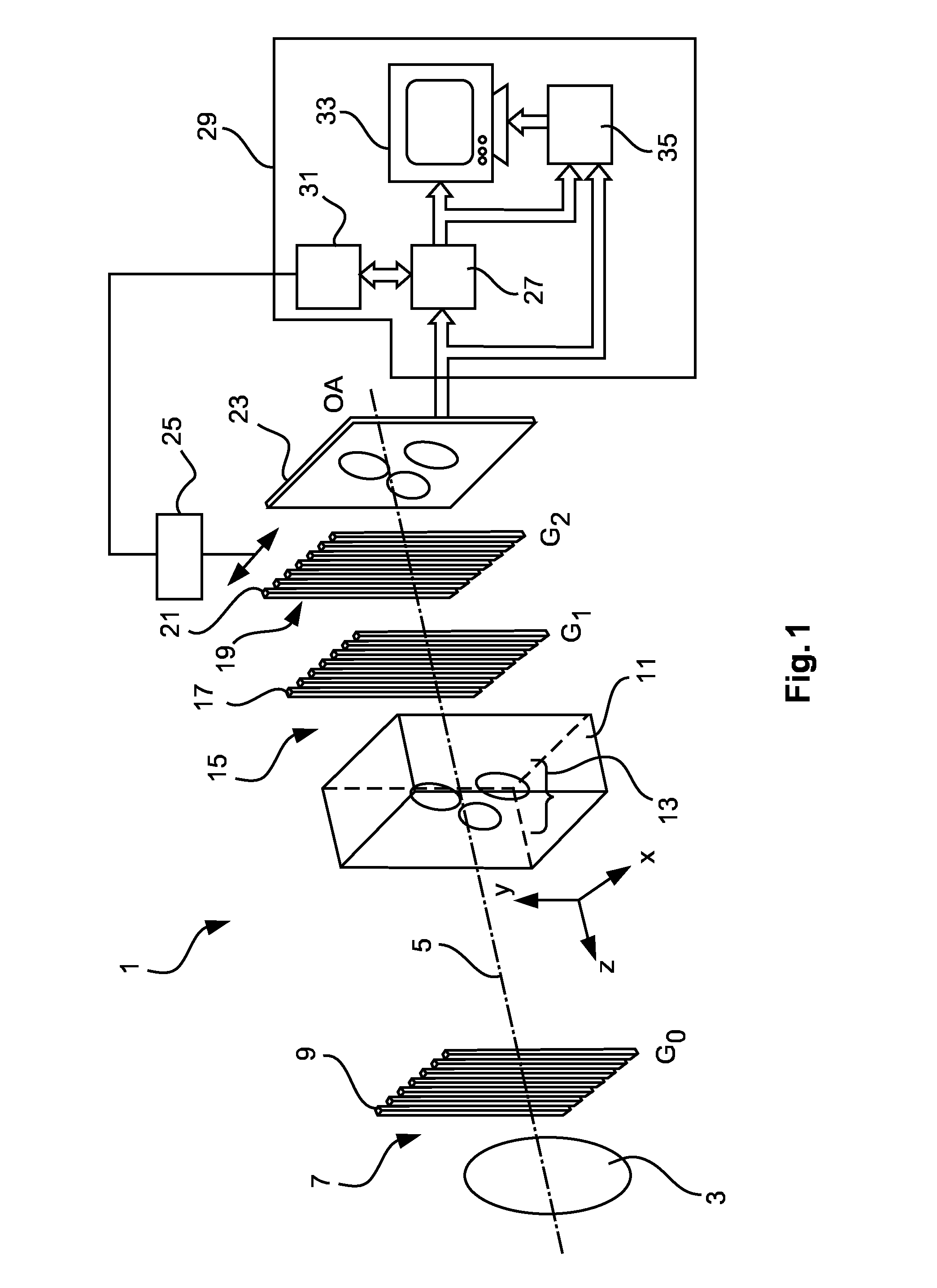
[0039]Introductorily, general principles and features of a differential phase contrast imaging apparatus 1 shall be described with reference to FIG. 1.

[0040]FIG. 1 shows an experimental DPCI grating interferometer setup for a Talbot-Laue type hard-X-ray imaging interferometer. An X-ray source 3 generates an X-ray beam 5 as schematically indicated in FIG. 1. The X-ray beam 5 extends in an emission direction z. Before reaching an examination volume 11 in which an object 13 to be examined may be positioned, the X-ray beam 5 is transmitted through a source grating 7, referred to as G0. The source grating 7 comprises multiple walls 9 extending like fingers in y-direction and being spaced from each other in x-direction. Using the source grating 7, an X-ray beam 5 having a specific spatial coherence may be generated from the X-ray beam originally coming from the incoherent X-ray source 3. After having been transmitted through the source grating 7, the X-ray beam 5 is transmitted through th...


PUM


Abstract

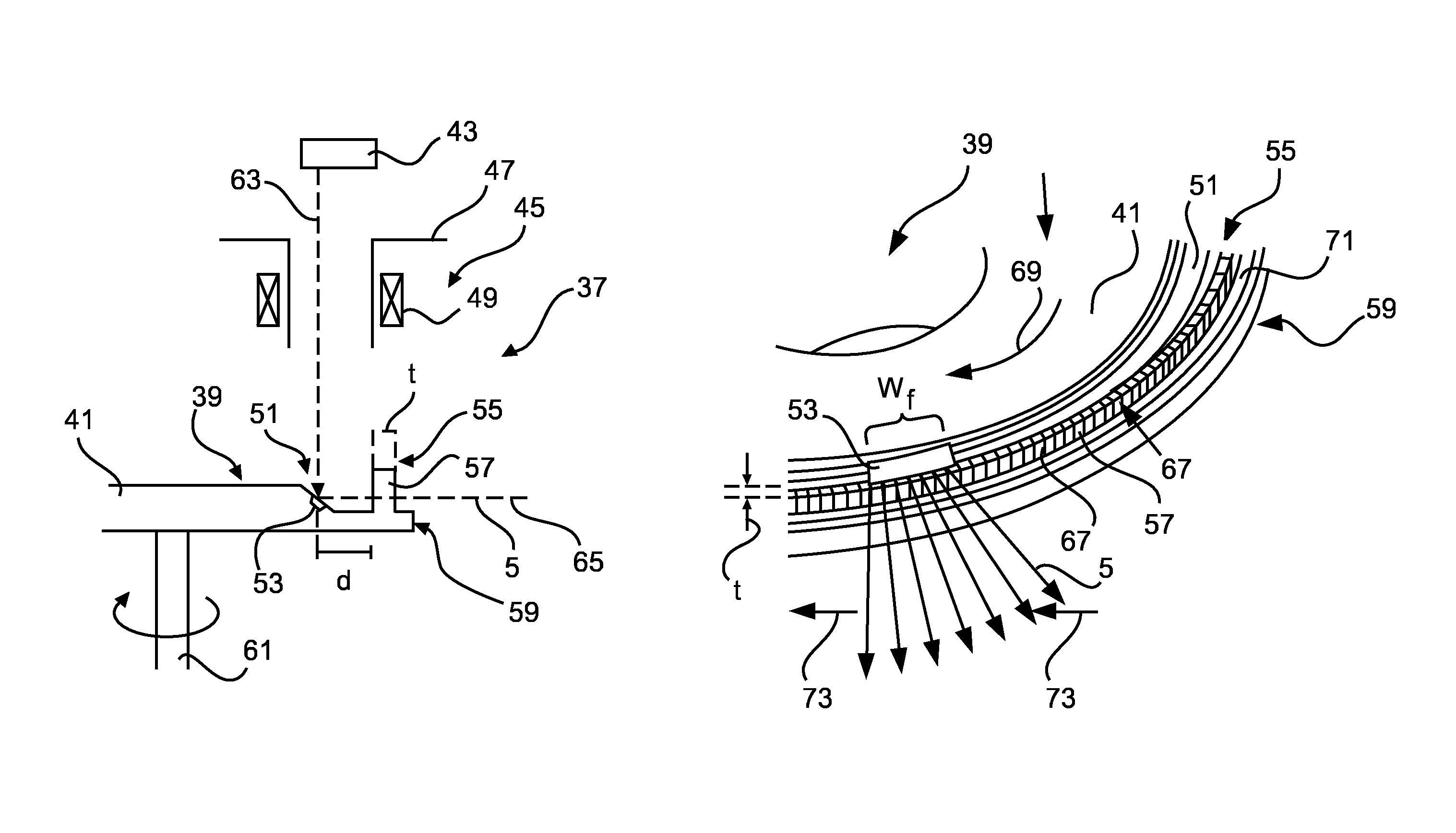
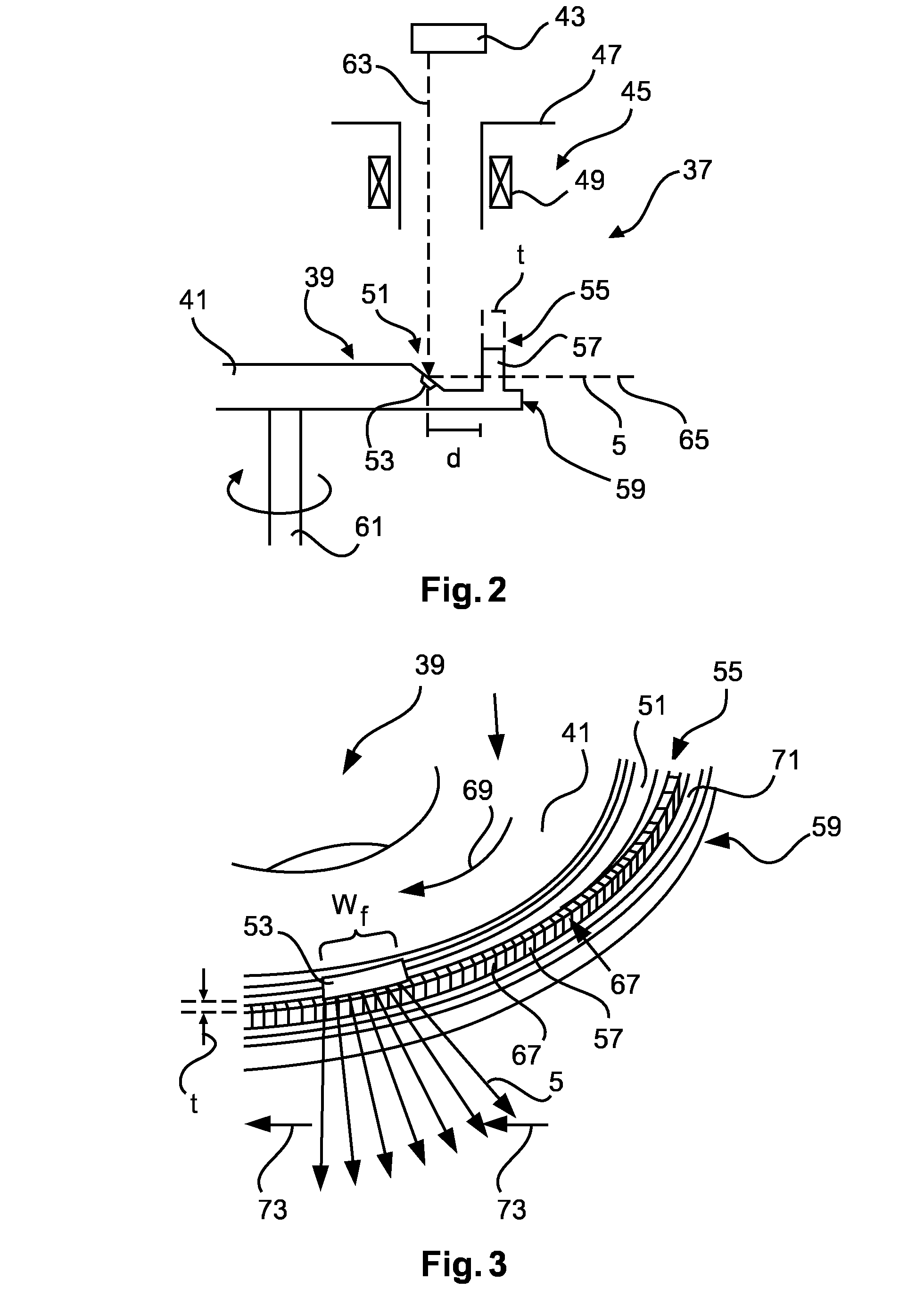
An Anode for an X-ray tube, comprising an anode disk comprising a circular focal track region being adapted to, upon impact of accelerated electrons, emit X-rays in an emission direction transverse to an impacting direction of the electrons; a ring-like modulating absorption grid; wherein the modulating absorption grid encloses the focal track region; wherein the modulating absorption grid comprises wall portions of X-ray absorbing material, the wall portions being arranged such as to absorb X-rays emitted from the focal track region in the emission direction; wherein the modulating absorption grid comprises slits between neighboring wall portions, the slits being arranged along a circumferential direction of the modulating absorption grid at spacings (s) of less than 100 μm and the slits having a width (ws) in the circumferential direction of less than 50 μm.

Description

CROSS-REFERENCE TO PRIOR APPLICATIONS[0001]This application is the U.S. National Phase application under 35 U.S.C. §371 of International Application No. PCT / EP2014 / 065657, filed on Jul. 22, 2014, which claims the benefit of European Patent Application No. 13177518.1, filed on Jul. 23, 2013. These applications are hereby incorporated by reference herein.FIELD OF THE INVENTION[0002]The present invention relates to an anode for an X-ray tube, an X-ray tube and a differential phase contrast imaging (DPCI) apparatus comprising such X-ray tube.BACKGROUND OF THE INVENTION[0003]X-ray tubes are provided for generating a beam of X-rays. This X-ray beam may be transmitted through an object of interest and the transmitted X-rays may be detected using an X-ray detector thereby providing information about X-ray absorbing characteristics of the object of interest. For example, X-ray tubes may be applied in medical imaging for visualizing internal structures of a region of interest in a patient.[00...

Claims


Application Information

Patent Timeline
Patent Type & Authority Patents(United States)
IPC IPC(8): G03H5/00H01J35/10G21K1/02
CPCG21K1/02H01J35/10G21K2207/005H01J2235/086
Inventor BEHLING, ROLF KARL OTTO
Owner KONINKLJIJKE PHILIPS NV
Learn More