
Electronic device and control method thereof

a technology of electronic devices and control methods, applied in the direction of amplifiers, low frequency amplifiers, manual operation of tone/bandwidth control, etc., can solve the problems of user inability to obtain desired sound quality, time-consuming, and electronic devices, and achieve the effect of rapid use of vacuum tubes and rapid preheating of vacuum tubes

Active Publication Date: 2016-08-09
SAMSUNG ELECTRONICS CO LTD
View PDF16 Cites 0 Cited by
  • Summary
  • Abstract
  • Description
  • Claims
  • Application Information

AI Technical Summary

Benefits of technology

This patent is about a new electronic device that can quickly heat up a vacuum tube when it is powered up for the first time. This helps to quickly get the device ready to use and ensures that it works properly. The patent also describes the method for controlling this device. The technical effect of this innovation is to provide a more efficient and effective tool for using vacuum tube audio amplifiers.

Problems solved by technology

However, there are several problems with using an electronic device including the vacuum tube audio amplifier.
Currently, in order to normally use a vacuum tube audio amplifier, it is necessary to preheat a vacuum tube, which takes time.
If the vacuum tube is not preheated, a user cannot obtain desired sound quality.
In the related art, a vacuum tube audio amplifier includes a heater which preheats a vacuum tube without using an additional circuit, which takes relatively long time for a general user.

Method used


Image

  • Electronic device and control method thereof
  • Electronic device and control method thereof
  • Electronic device and control method thereof

Examples


Embodiment Construction

[0024]Below, exemplary embodiments will be described in detail with reference to accompanying drawings so as to be easily realized by a person having ordinary knowledge in the art. The exemplary embodiments may be embodied in various forms without being limited to the exemplary embodiments set forth herein. Descriptions of well-known parts are omitted for clarity, and like reference numerals refer to like elements throughout.

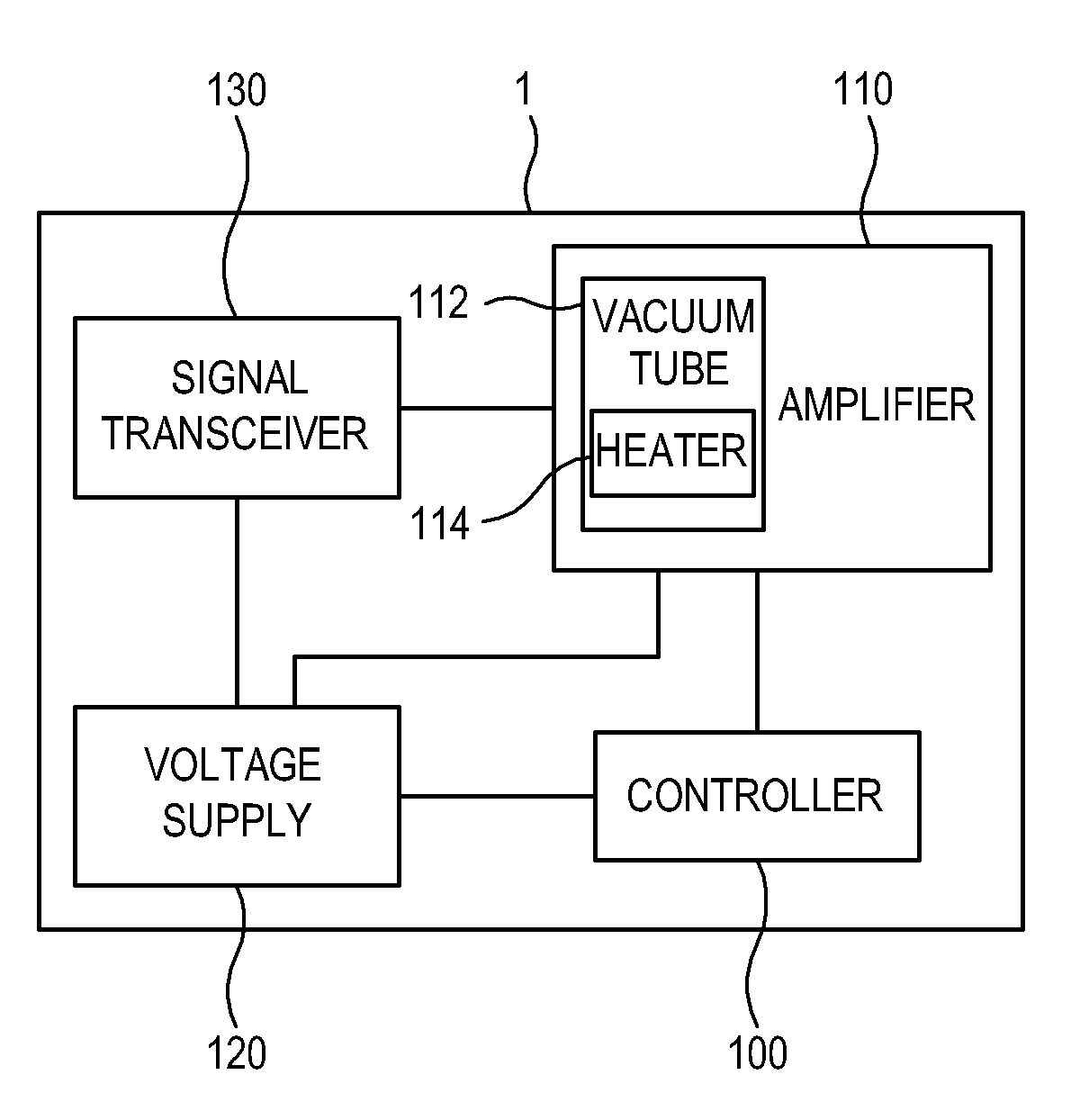
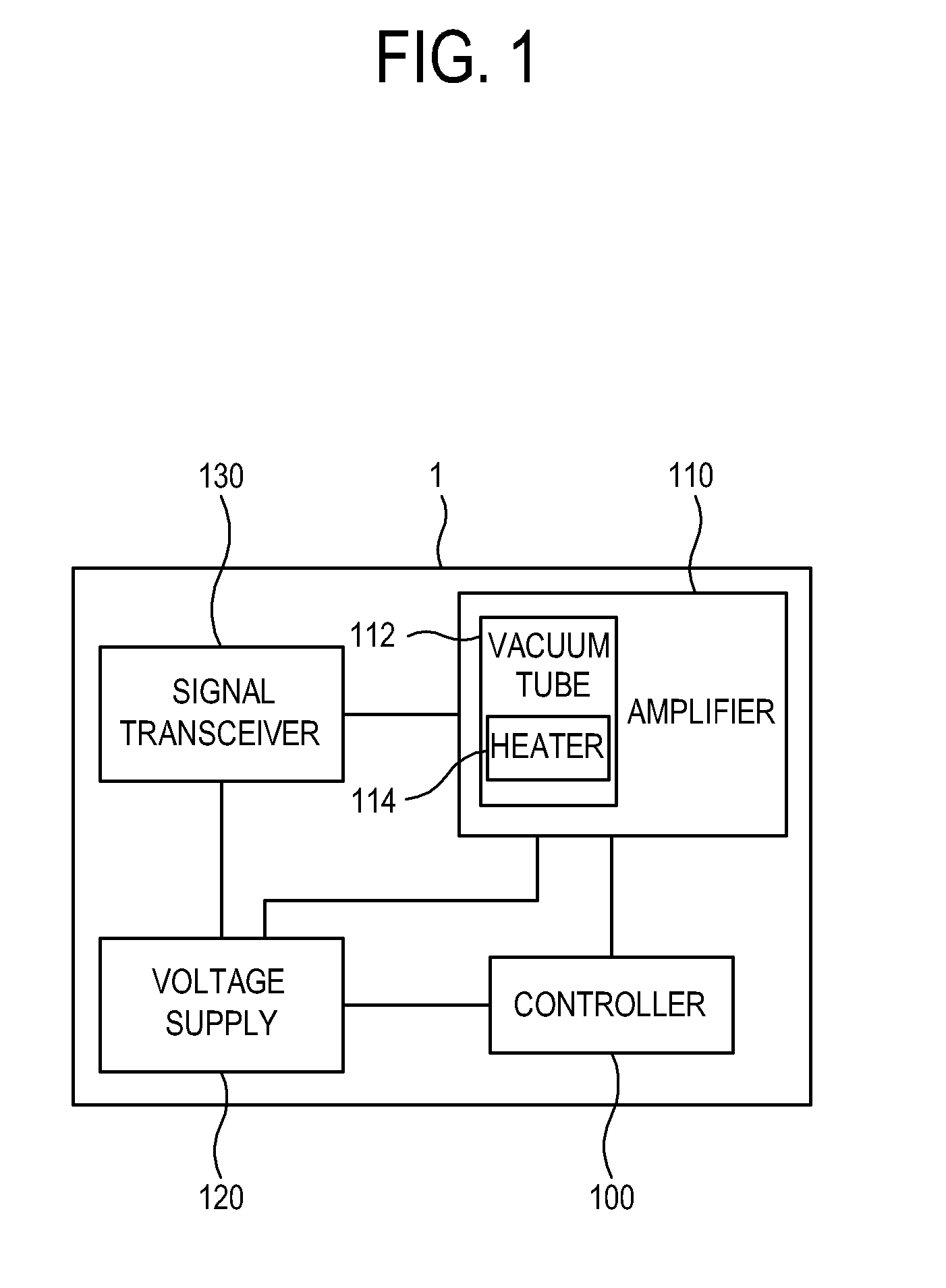
[0025]FIG. 1 is a block diagram illustrating a configuration of an electronic device 1 according to an exemplary embodiment. As shown in FIG. 1, the electronic device 1 may include an amplifier 110, a voltage supply 120, a controller 100, and a signal transceiver 130.

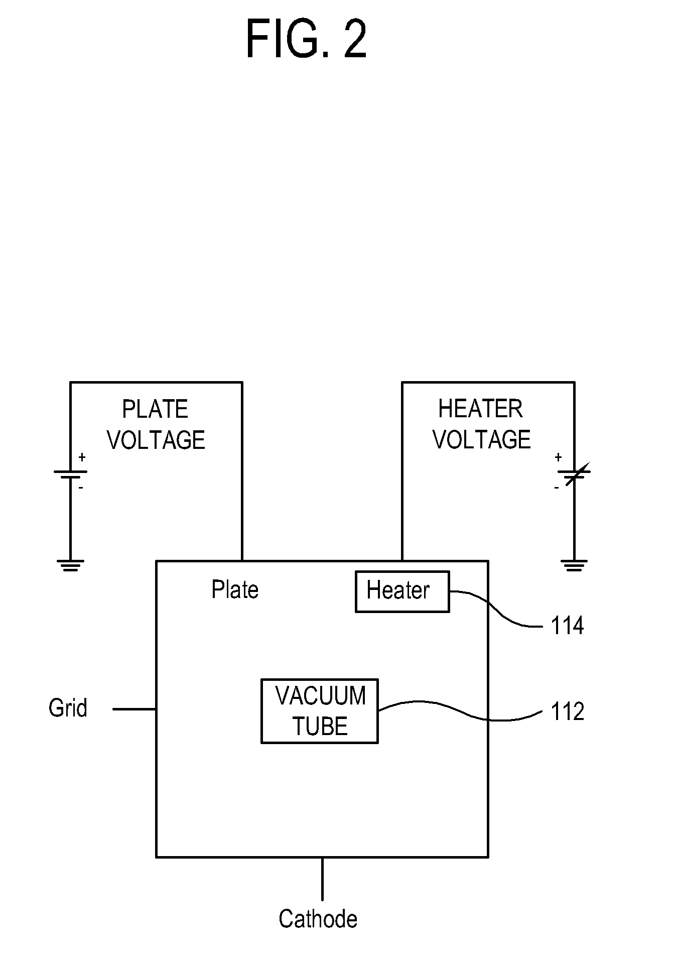
[0026]In the electronic device 1, the amplifier 110 may include a vacuum tube 112 which amplifies a sound signal, and the vacuum 112 may include a heater 114. The voltage supply 120 may supply one of a first voltage and a second voltage, which is higher than the first voltage, to the heater 114. The...


PUM


Abstract

An electronic device includes an amplifier which is configured to amplify a sound signal and includes a vacuum tube including a heater configured to heat the vacuum tube; a voltage supply which is configured to supply a first voltage and a second voltage which is higher than the first voltage; and a controller which is configured to control the voltage supply to supply the second voltage to the heater in response to supply of a drive voltage to the amplifier being started and to supply the first voltage to the heater if the vacuum tube reaches a predetermined temperature.

Description

CROSS-REFERENCE TO RELATED APPLICATION[0001]This application claims priority from Korean Patent Application No. 10-2012-0152197, filed on Dec. 24, 2012 in the Korean Intellectual Property Office, the disclosure of which is incorporated herein by reference.BACKGROUND[0002]1. Field[0003]Apparatuses and methods consistent with exemplary embodiments relate to an electronic device and a control method thereof, and more particularly to an electronic device which can rapidly preheat a vacuum tube in an initial operation of the electronic device for rapid use of a vacuum tube audio amplifier, and a control method thereof.[0004]2. Description of the Related Art[0005]Many people enjoy listening to music using a vacuum tube audio amplifier. However, there are several problems with using an electronic device including the vacuum tube audio amplifier.[0006]Currently, in order to normally use a vacuum tube audio amplifier, it is necessary to preheat a vacuum tube, which takes time. If the vacuum ...

Claims


Application Information

Patent Timeline
Patent Type & Authority Patents(United States)
IPC IPC(8): H03F1/00H03F3/02H03F3/181H03F3/20H03F5/00
CPCH03F3/02H03F3/181H03F3/20H03F5/00H03G5/06
Inventor LEE, JAE-CHEOLKIM, BYUNG-SOOYOUN, JOO-MOONCHO, KEE-YEONG
Owner SAMSUNG ELECTRONICS CO LTD
Learn More