LED light control assembly and system

a technology of led light and assembly, applied in the field of light-emitting diodes, can solve the problem that the light signals are not observable to the unaided eyes of individuals, and achieve the effect of reducing the number of people in the room

Active Publication Date: 2016-08-09
FEDERAL LAW ENFORCEMENT DEV SERVICES
View PDF473 Cites 9 Cited by
  • Summary
  • Abstract
  • Description
  • Claims
  • Application Information

AI Technical Summary

Benefits of technology

[0021]According to one embodiment of the invention, there is provided an illumination apparatus that is capable of illuminating a space and simultaneously capable of communicating through visible light directly with a number of adjunct devices. In addition to human communications, communications with adjunct devices may effect various convenience, security, energy management and related functions. The illumination apparatus further enables control over intensity, color, and temperature of light without requiring any physical change of the illumination apparatus.
[0023]Light Emitting Diodes, or LEDs, provide with other apparatus a communications channel while simultaneously affording flexible illumination within a space or building. Using LEDs to provide visible lighting and to embed communications therein enables the present invention to improve security and provide higher communication and / or data transmission capacity as compared to lighting systems as known. The LED link is untethered and enables a communication link with nomadic devices. The link is untethered in that the user is independent of any one host, and may get the same information at other optical hosts locations.
[0024]A VLEC system designed in accord with the teachings of the present invention may interface with new or existing building internal electrical wiring. By positioning architectural lighting fixtures that perform dual functions as VLEC and / or server optical transceiver (XCVR) transceivers, a building space may be efficiently illuminated while accomplishing high-speed secure wireless data communication. In some embodiments, a VLEC and an XCVR may be used interchangeably. The LEDs that are incorporated into VLEC transceivers are environmentally friendly and relatively insensitive to atmospheric conditions. A VLEC system has the added benefit of communicating by pulsing the LEDs in such a way as to communicate data at nearly the same rate or capacity, or a faster rate or capacity, as compared to modern fiber optic channels.
[0025]Embodiments designed in accord with the teachings of the present invention may be fully integrated into existing networks and infrastructures presently in use. Security and access levels may be controlled on the back end of a network by employing known equipment such as a firewalls, routers and hubs. Embodiments of the present invention are meant to improve and compliment communication areas that fall short in today's existing infrastructure, from full duplex communications of voice to ultra high speed broadband packet data transfers for full motion video, on highly reliable, scalable, stable and fully redundant infrastructures. Most deployments are easily started by taking advantage of existing infrastructures and applying low cost fill-in or gap solutions. Many modulations schemes are available today, such as CDMA, OFDM, TDM, PWM, PPM, PDM, AM, BPSK and specific layers of QAM, to name a few, which may be used in conjunction with the present invention. Low-power BPL / PLC systems may be used to provide high speed digital communications capabilities by coupling RF energy onto the power lines inside a building. In addition, higher speeds than available from existing Access BPL technology may be obtained in the preferred embodiments by encasing the electrical wire in conduit, thereby implementing Shielded BPL (S-BPL) in accord with the present teachings.

Problems solved by technology

The light signals are not observable to the unaided eyes of an individual.
It is commonly known that the last mile of most systems is responsible for the vast majority of expense and difficulty in establishing and maintaining a communication system.

Method used


Image

  • LED light control assembly and system
  • LED light control assembly and system
  • LED light control assembly and system

Examples


Embodiment Construction

[0067]While this invention may be embodied in many different forms, there are described in detail herein specific alternative embodiments of the invention. This description is an exemplification of the principles of the invention and is not intended to limit the invention to the particular embodiments illustrated. For the purposes of this disclosure, like reference numerals in the figures shall refer to like features unless otherwise indicated.

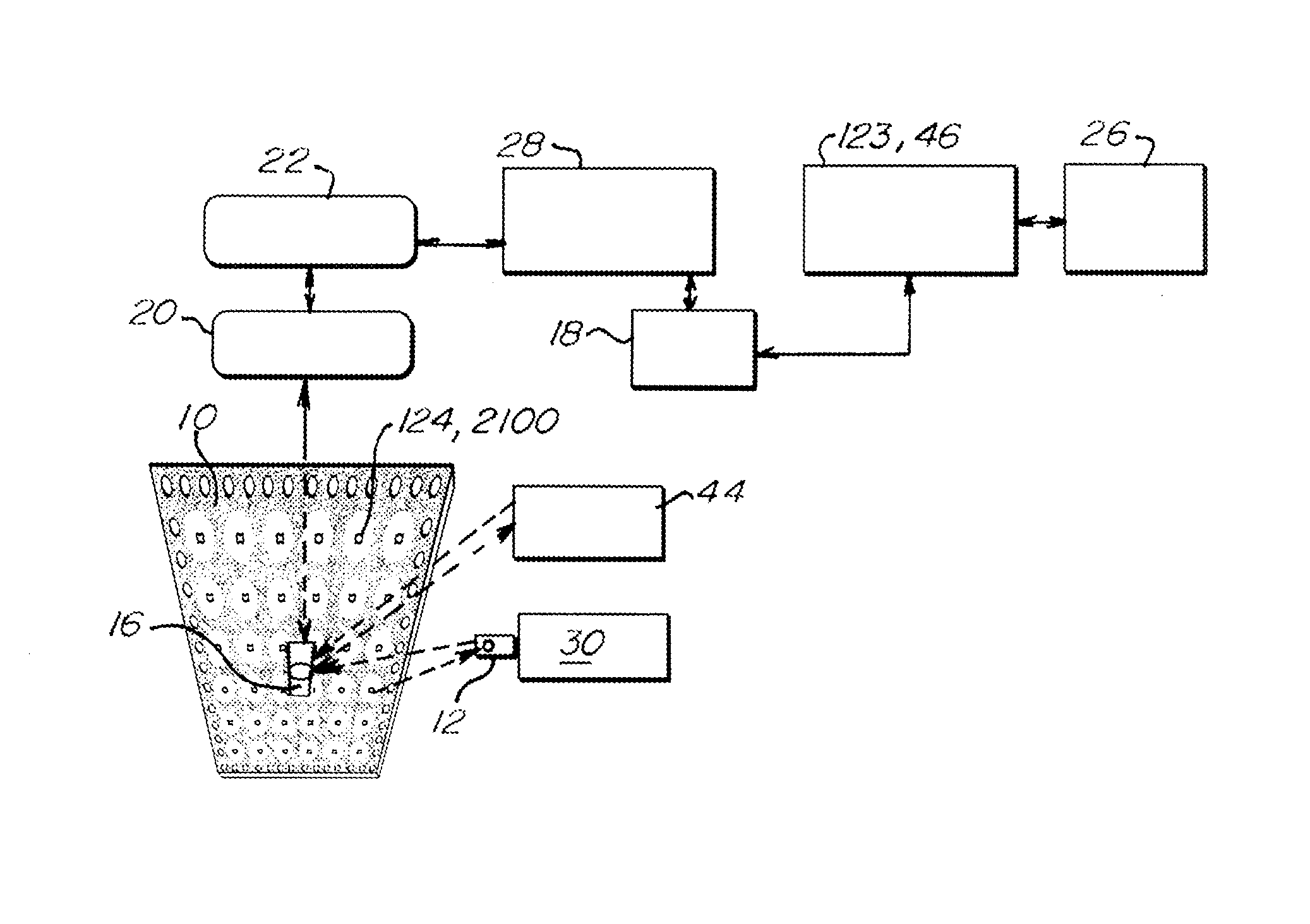
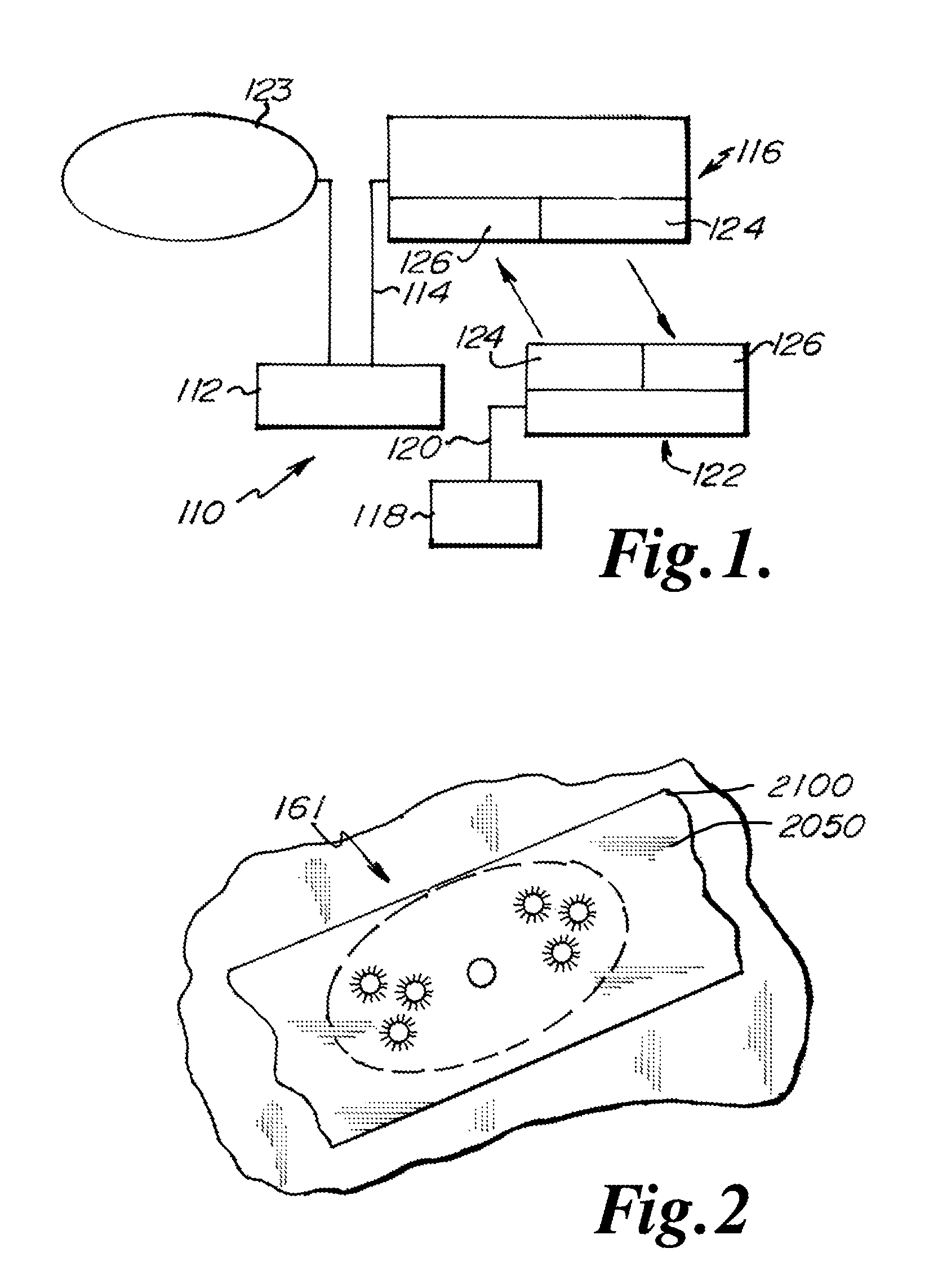
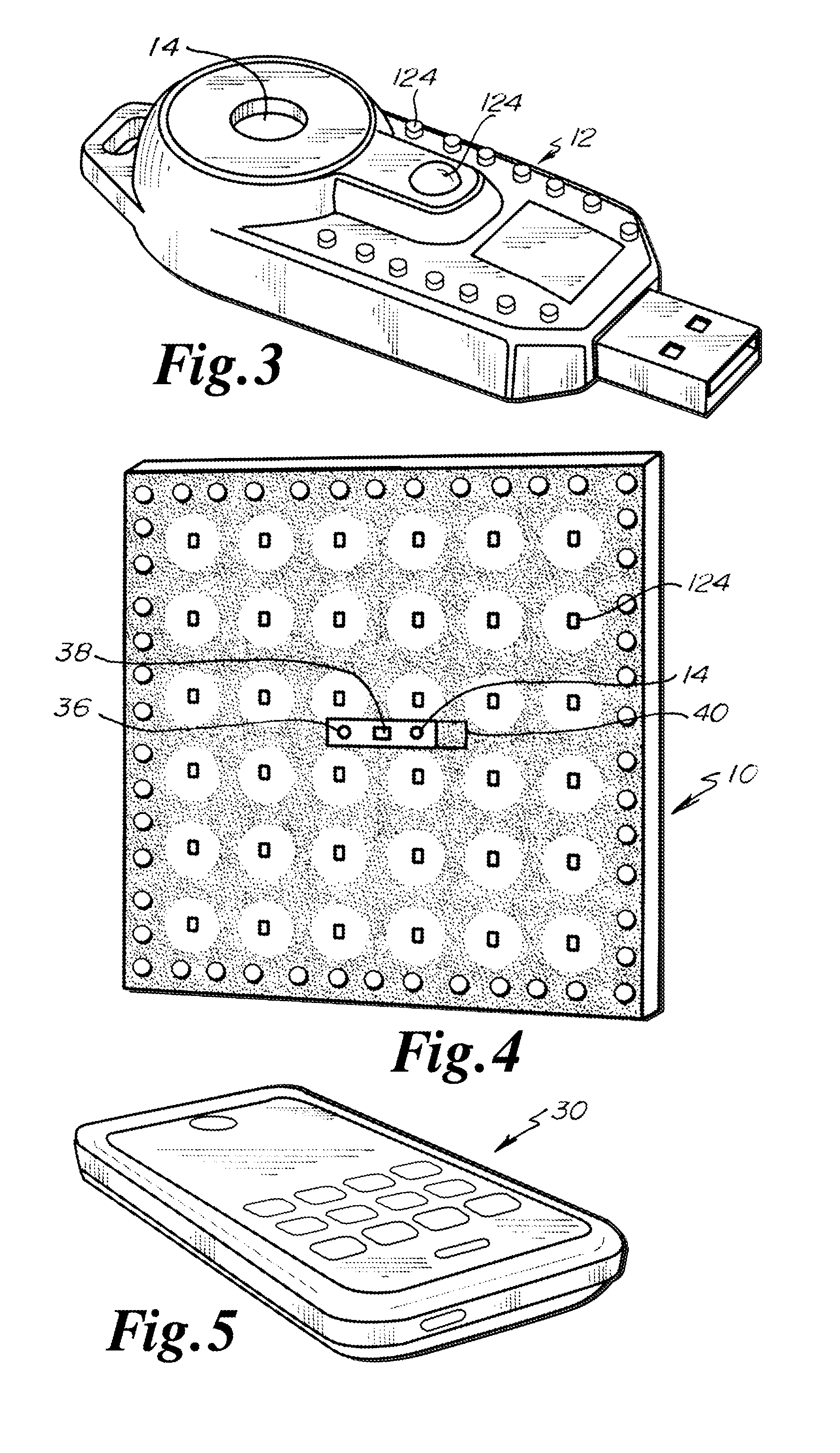
[0068]In each of the embodiments discussed below, the LEDs 124, 2100 may be formed of the same or different colors. The LED's 124, 2100 are in communication with a controller 20 which may be configured to select the color of the LEDs 124, 2100 to be illuminated forming the light signal.

[0069]It should be noted that in some embodiments, the LED's 124, 2100 can both emit and receive light. In such an embodiment, the LED's 124, 2100 can act both as a transmitter or receiver. More information on such bi-directional LEDs can be found in U.S. Pat. N...


PUM


Abstract

An LED light and communication system is in communication with a broadband over power line communications system. The LED light and communication system includes at least one optical transceiver light fixture. The optical transceiver light fixture includes a plurality of light emitting diodes, at least one photodetector, and a processor. A facility control unit is in communication with the light emitting diode light fixtures and a control server. The facility control unit is constructed and arranged to control the operation of the optical transceiver light fixtures.

Description

CROSS-REFERENCE TO RELATED APPLICATIONS[0001]This application claims priority to Provisional Application No. 61 / 927,638, filed Jan. 15, 2014, the disclosure of which is expressly incorporated herein by reference.[0002]This application is also a continuation-in-part of U.S. patent application Ser. No. 14 / 208,125 filed on Mar. 13, 2014 which claims benefit of 61 / 778,672, filed Mar. 13, 2013. This application is also a continuation-in-part of U.S. patent application Ser. No. 13 / 427,358, filed Mar. 22, 2012, now U.S. Pat. No. 8,744,267 which is a continuation of U.S. patent application Ser. No. 12 / 126,342 filed May 23, 2008 now abandoned which claimed priority to U.S. Provisional Patent Application Ser. No. 60 / 931,611 filed May 24, 2007 the disclosures all of which are expressly incorporated by reference herein in their entireties.[0003]This application is a continuation-in-part of U.S. patent application Ser. No. 14 / 270,670 filed May 6, 2014 which claims benefit of 61 / 819,861 filed May...

Claims


Application Information

Patent Timeline
Patent Type & Authority Patents(United States)
IPC IPC(8): H04B10/00H05B33/08H04B10/114H04B10/116H04J14/00H05B44/00
CPCH05B33/0863H05B33/0869H04B10/1143H04B10/1149H04B10/116H05B33/0845H05B45/22H05B45/20H05B47/12H05B47/11Y02B20/40H05B47/195H05B47/125
Inventor PEDERSON, JOHN C.
Owner FEDERAL LAW ENFORCEMENT DEV SERVICES
Why Eureka
Try Eureka