Image forming apparatus configured to switch between supplying and shutting-off of power to a portion of the image forming apparatus

a technology power supply, applied in the field of image forming apparatus, can solve problems such as excessive current passing

Active Publication Date: 2016-08-16
CANON KK
View PDF13 Cites 0 Cited by
  • Summary
  • Abstract
  • Description
  • Claims
  • Application Information

AI Technical Summary

Benefits of technology

[0007]According to an aspect of the present invention, an image forming apparatus is capable of stopping power supply from a second power supply unit when an overcurrent flows from the second power supply unit, and preventing the image forming apparatus from losing data by a control unit, to which power is supplied from a first power supply unit, executing finish processing.

Problems solved by technology

A short circuit, which may be caused by reasons such as a failure of an electronic component to which the second power supply unit supplies power, would lead to passage of an excessive current if the second power supply unit maintains the output voltage.

Method used


Image

  • Image forming apparatus configured to switch between supplying and shutting-off of power to a portion of the image forming apparatus
  • Image forming apparatus configured to switch between supplying and shutting-off of power to a portion of the image forming apparatus
  • Image forming apparatus configured to switch between supplying and shutting-off of power to a portion of the image forming apparatus

Examples


Embodiment Construction

[0017]Exemplary embodiments of the invention will now be described with reference to the drawings.

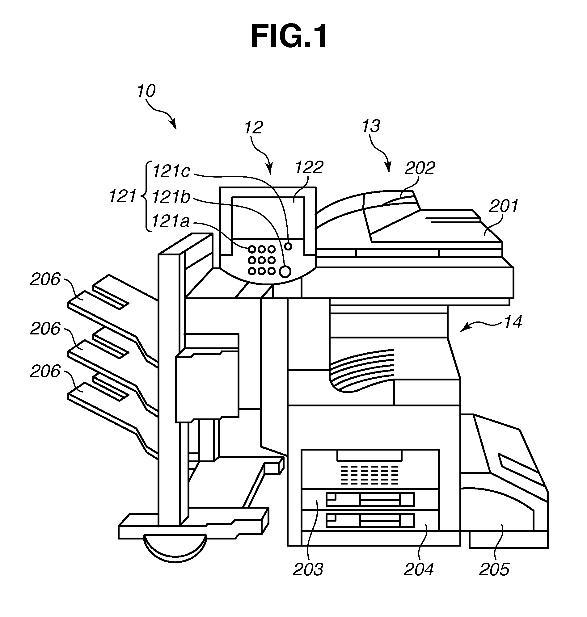
[0018]FIG. 1 is a diagram illustrating an external appearance of an image forming apparatus according to a first exemplary embodiment of the present invention.

[0019]As illustrated in FIG. 1, an image forming apparatus 10 includes an operation unit 12, which is a user interface (UI), a scanner unit 13, which is an image input device, and a printer unit 14, which is an image output device.

[0020]The operation unit 12 includes various buttons 121 to be operated by a user and a display unit 122 to display an image. The display unit 122 displays screens, such as a status screen to display a status of the image forming apparatus 10 and a setting screen for the user to input information needed to execute a copy function and a fax function. The buttons 121 include a button 121a to allow inputting of the number of print copies and the like, a start button 121b to start copying, fax transmission, ...


PUM


Abstract

An image forming apparatus includes a first power supply unit to output first output power, a first device to which the first output power is supplied, a second power supply unit to output second output power, a second device to which the second output power is supplied, a detection unit to detect an overcurrent of the second power supply unit, a power source control unit to which the first output power is supplied and to switch between supplying and shutting-off of the second output power to the second device, and a control unit to which the first output power is supplied and to control an operation of the power source control unit. When the detection unit detects an overcurrent of the second output power, the power source control unit shuts off the second output power to the second device, and the control unit executes finish processing for the first device.

Description

BACKGROUND OF THE INVENTION[0001]1. Field of the Invention[0002]The present invention relates to an image forming apparatus including a detection unit that detects an overcurrent.[0003]2. Description of the Related Art[0004]An image processing apparatus (image forming apparatus) which stops supplying power to a printer unit to reduce standby power consumption during standby in which a printing function is not executed (Japanese Patent Application Laid-Open No. 2001-109546), is known. The image processing apparatus discussed in Japanese Patent Application Laid-Open No. 2001-109546 includes a slave CPU, to which a first power supply unit supplies power regardless of a state (an on / off state) of a power switch operated by a user. The image processing apparatus also includes a master CPU, to which a second power supply unit supplies power when the power switch is on. In addition to the master CPU, the second power supply unit also supplies power to a copy function control unit that cont...

Claims


Application Information

Patent Timeline
Patent Type & Authority Patents(United States)
IPC IPC(8): G03G15/00
CPCG03G15/80G03G15/5004
Inventor UMIMURA, KIYOKAZU
Owner CANON KK
Why Eureka
Try Eureka