Portable electronic device to a docking station with improved docking and retention features

a technology of electronic devices and docking stations, applied in the direction of electrical equipment casings/cabinets/drawers, instruments, computing, etc., can solve the problems of unfavorable comparison to desktop computers in some respects, portability of portable computers may not have keyboards, mouses, printers, etc., to improve the security of the docked portable electronic devices, simplify the docking station, and reduce the number of steps

Active Publication Date: 2016-08-30
ZEBRA TECH CORP
View PDF2 Cites 31 Cited by
  • Summary
  • Abstract
  • Description
  • Claims
  • Application Information

AI Technical Summary

Benefits of technology

[0019]According to one embodiment, the support surface of the docking station may include one or more magnetic structures, which are positioned to align with one or more magnetic structures on the back surface of the portable electronic device and configured to provide a magnetic force to retain the portable electronic device on the support surface. The strength of the magnetic force may generally depend on the size and number of magnetic structures used, and the location of the magnetic structures provided. In general, the magnetic structures may be configured and positioned to provide a magnetic force, which is strong enough to reliably retain the portable electronic device on the support surface of the docking station when the docking station is rotated, pivoted or moved, or used in a vehicular environment. In some embodiments, the use of magnetic structures to retain the portable electronic device may simplify the docking station by eliminating the need to include a mechanical latch and reducing the number of steps the user has to perform to dock and undock the portable electronic device.
[0020]Although a mechanical latch may be omitted in preferred embodiments, a mechanical latch is not precluded from the design. In some embodiments, a mechanical latch with a locking mechanism (e.g., a key lock, biometric scanner, keypad, etc.) may be included on the docking station for enhancing the security of the docked portable electronic device, and may be desirable in environments where security is a concern. One exemplary embodiment of such a latch is described in co-pending application Ser. No. 14 / 667,149, which is entitled “Docking Station with Improved Latching Mechanism” and incorporated herein in its entirety. Other mechanical latches may also be included on the docking station, if so desired. However, these mechanical latches are generally not necessary, if only retention is desired. In most cases, the magnetic structures described herein are sufficient to reliably retain the portable electronic device on the support surface of the docking station.
[0021]In addition to reliably retaining the portable electronic device, the one or more magnetic structures respectfully positioned on the support surface of the docking station and the back surface of the portable electronic device may increase the compressive force applied to the docking connectors to mechanically engage the docking connectors, and therefore, decrease the electrical impedance there between. Although the magnetic structures may be positioned in substantially any location, it may be desirable to position the magnetic structures substantially away from the rotational axis of the rotating cradle to increase the compressive force applied to the docking connectors. In one embodiment, the magnetic structures may be arranged near the top edge (or top corners) of the support surface of the docking station. In some embodiments, one or more magnetic structures may also be arranged near the bottom edge (or bottom corners) of the support surface to further assist in aligning and retaining the portable electronic device onto the support surface, and / or for increasing the compressive force applied to the docking connectors.
[0022]According to another embodiment, a portable electronic device comprising one or more magnetic structures on a back surface of the portable electronic device is provided herein. In general, the one or more magnetic structures may be positioned to align with one or more magnetic structures located on a support surface of a docking station. When the portable electronic device is docked, the magnetic structures may generally function to align and retain the portable electronic device onto the support surface of the docking station. The magnetic structures may also function to increase the compressive force applied to the docking connectors of the portable electronic device and the docking station to mechanically engage the docking connectors and reduce the electrical impedance there between.
[0023]In one embodiment, the one or more magnetic structures positioned on the back surface of the portable electronic device may be arranged near the top edge (or top corners) of the back surface. In some embodiments, one or more magnetic structures may also be arranged near the bottom edge (or bottom corners) of the back surface of the portable electronic device to further assist in aligning and retaining the portable electronic device on the support surface, and / or for increasing the compressive force applied to the docking connectors.

Problems solved by technology

Portable computers are generally lightweight and compact, but may compare unfavorably to desktop computers in some respects because they are generally equipped with smaller keyboards and displays.
Further, some portable computers may not have a keyboard, mouse, printer ability, local area network (LAN) connection, or an optical drive.
Because of the complexity and repeated mechanical connection and disconnection of this connector, the connector is susceptible to fatigue related failure.
Docking connectors may also be damaged by frictional forces that occur during docking when a portable electronic device or computer is slid into a receptacle of a docking station.
While it does have the ability to retain and align the portable computer onto a surface of the docking station, the mechanical latch often involves a complex mechanism that requires an extra step to disengage before the portable computer can be removed from the docking station.

Method used


Image

  • Portable electronic device to a docking station with improved docking and retention features
  • Portable electronic device to a docking station with improved docking and retention features
  • Portable electronic device to a docking station with improved docking and retention features

Examples


Embodiment Construction

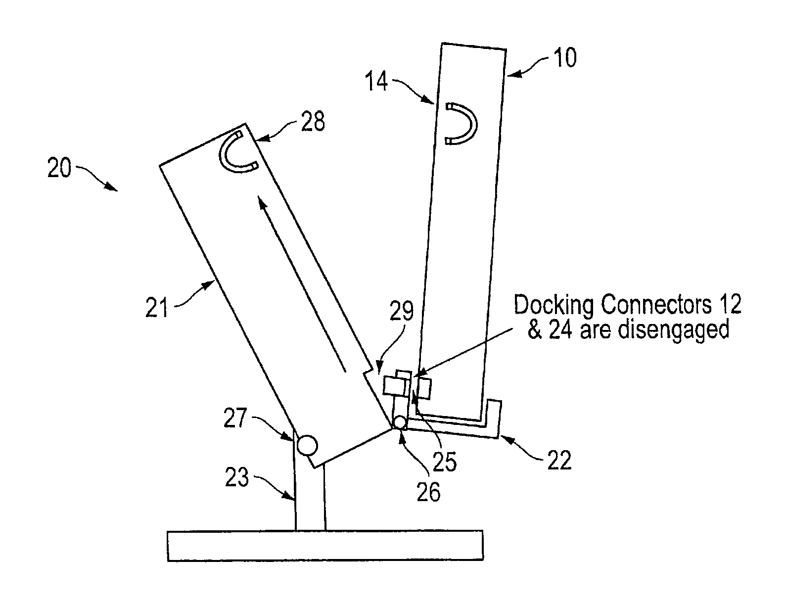
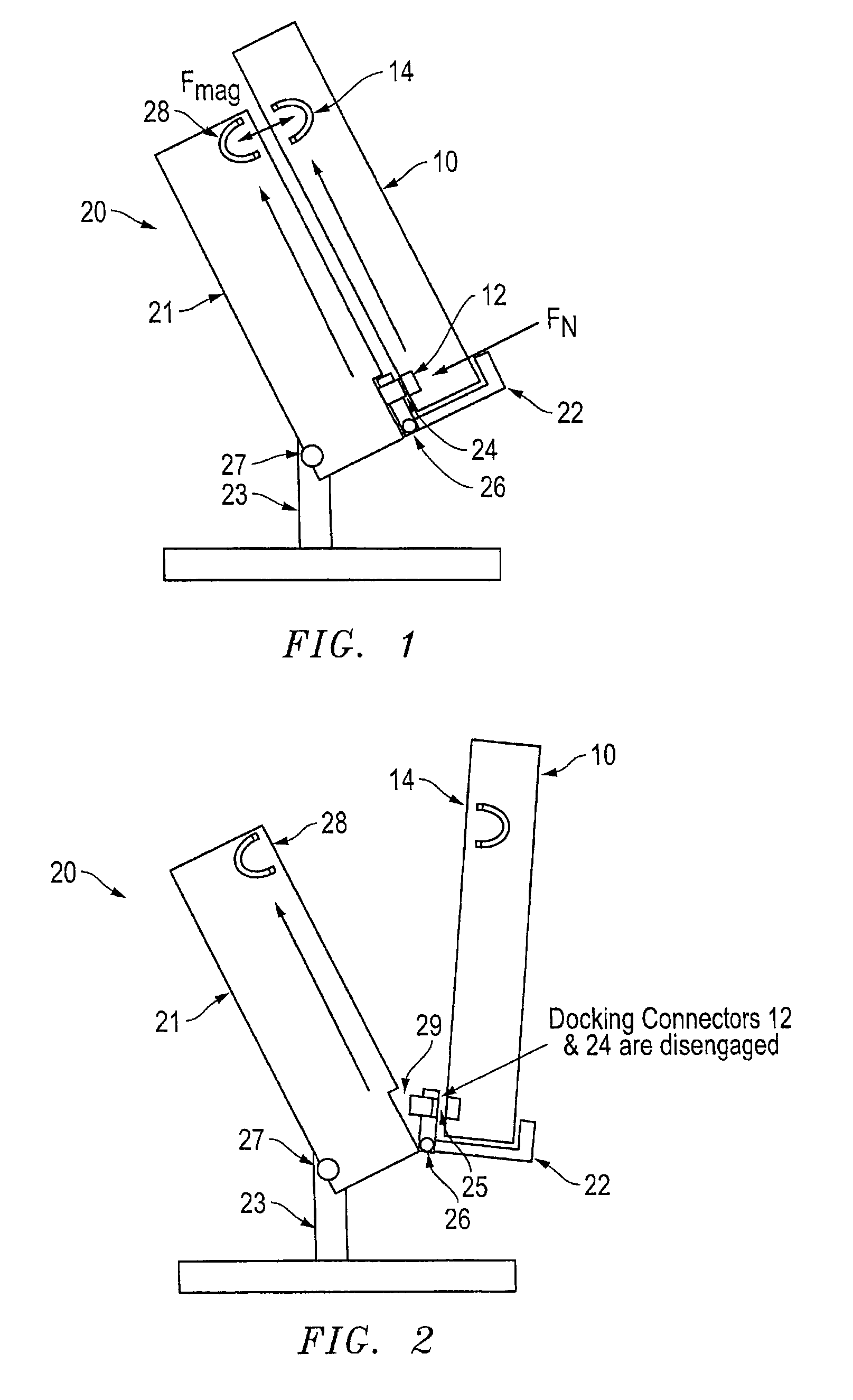
[0037]FIGS. 1-10 illustrate one embodiment of an improved docking station having features that not only assist in aligning and engaging the docking connectors of a portable electronic device and docking station, but also reliably retain the portable electronic device against a support surface of the docking station at all viewing angles and in all environments. The improved docking station represents a significant improvement over conventional docking stations by omitting the complex mechanical latch mechanism typically used on these devices to retain the portable electronic device, thereby reducing the number of steps the user has to perform to dock and undock the portable electronic device. While the present invention is particularly well suited to tablet PCs, and is described as such below, the inventive concepts disclosed herein could be used with other portable electronic devices that can be docked.

[0038]FIG. 1 is a side view block diagram of a portable electronic device 10, wh...


PUM


Abstract

According to one embodiment, a docking station is provided with a support surface configured for supporting a back surface of a portable electronic device, a rotating cradle configured for receiving a base of the portable electronic device, and a floating docking connector that extends out of a recess of the rotating cradle for connecting to a docking connector of the portable electronic device. According to one embodiment, the support surface of the docking station may include one or more magnetic structures, which are positioned to align with one or more magnetic structures on the back surface of the portable electronic device and configured to provide a magnetic force to retain the portable electronic device on the support surface.

Description

PRIORITY CLAIM[0001]The present application claims priority to U.S. Provisional Application No. 61 / 969,437 filed Mar. 24, 2014.BACKGROUND OF THE INVENTION[0002]1. Field of the Invention[0003]The present invention relates to portable electronic devices and docking stations for docking such devices. More specifically, the present invention relates to a mechanism that improves docking by using a rotational movement to generate a compressive force for engaging docking connectors on the portable electronic device and docking station, while reducing frictional forces on the connectors. The present invention further relates to a portable electronic device and docking station that uses a magnetic force to retain the portable electronic device against a support surface of the docking station and to increase the compressive force applied to docking connector to achieve a more reliable electrical connection.[0004]2. Description of the Related Art[0005]The following descriptions and examples ar...

Claims


Application Information

Patent Timeline
Patent Type & Authority Patents(United States)
IPC IPC(8): H05K5/00G06F1/16
CPCG06F1/1632G06F1/1656
Inventor VIER, BRADFORD EDWARD
Owner ZEBRA TECH CORP
Why Eureka
Try Eureka