

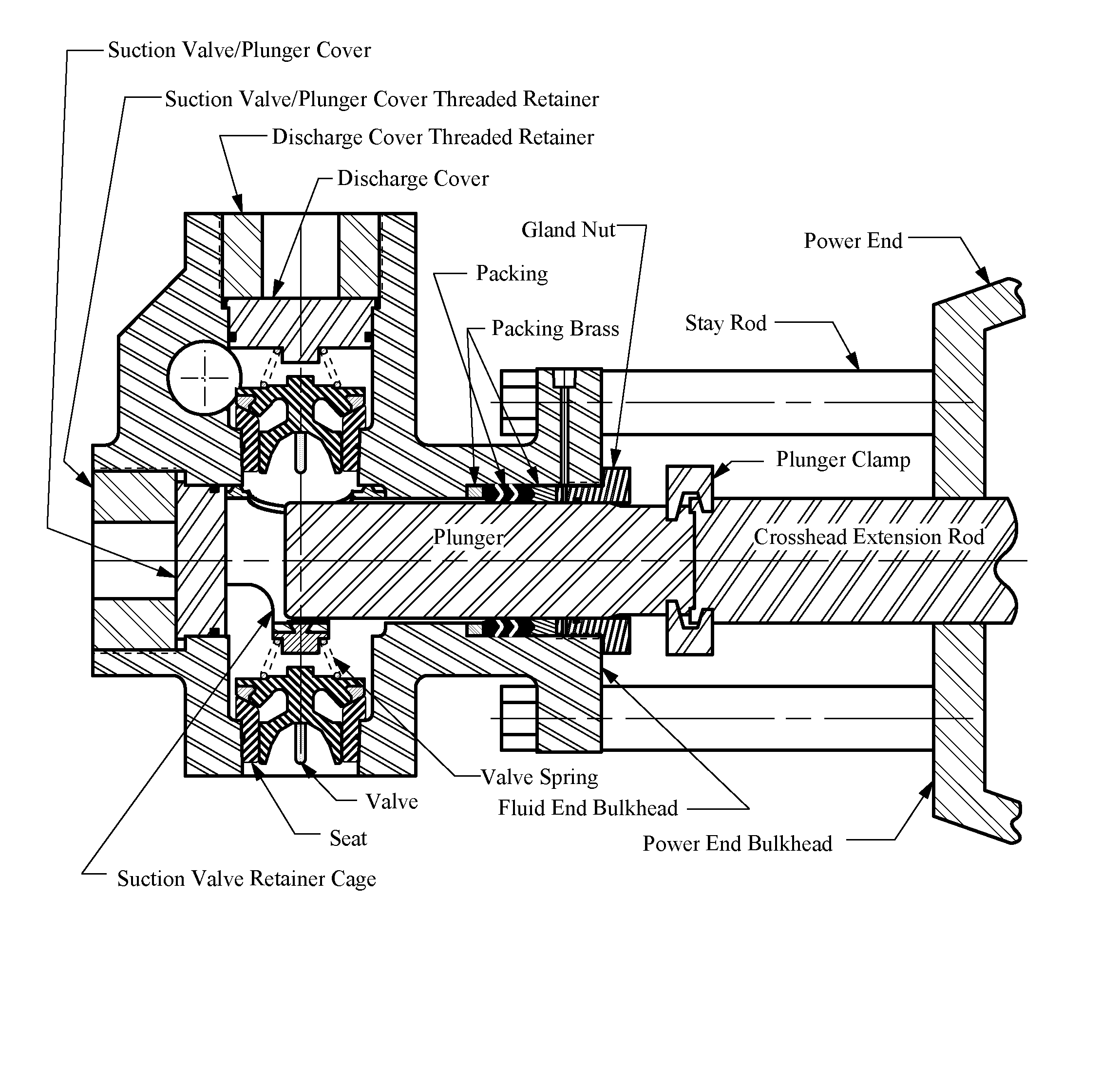
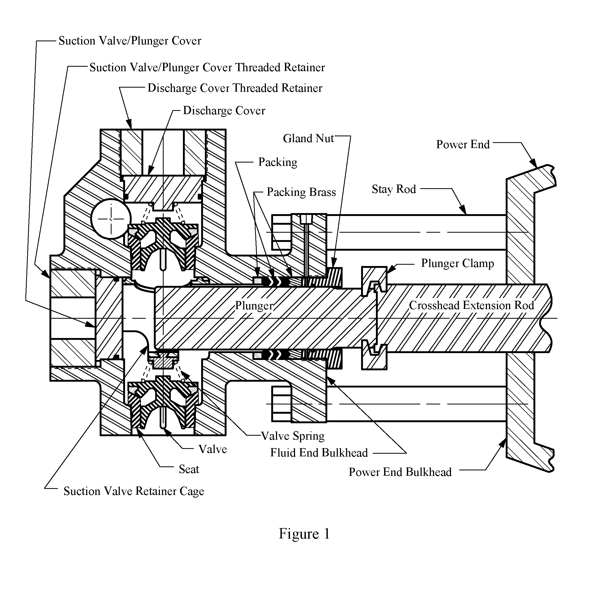
Fluid end with carbide valve seat and adhesive dampening interface
a technology of carbide valve seat and rubber dampening interface, which is applied in the direction of functional valve types, machines/engines, liquid fuel engines, etc., can solve the problems of inapplicability of tungsten carbide or ceramic inlays
- Summary
- Abstract
- Description
- Claims
- Application Information
AI Technical Summary
Benefits of technology
Problems solved by technology
Method used
Image

Examples
Embodiment Construction
[0050]Embodiments of the disclosure provide systems and methods for assembling and installing tungsten carbide seats in high pressure oilfield well service pumps. Various illustrative embodiments of the present invention will now be described in detail with reference to the accompanying figures. While various details are set forth in the following description, it will be appreciated that the present invention may be practiced without these specific details, and that numerous implementation-specific decisions may be made to the invention described herein to achieve the inventor's specific goals, such as compliance with process technology or design-related constraints, which will vary from one implementation to another. While such a development effort might be complex and time-consuming, it would nevertheless be a routine undertaking for those of skill in the art having the benefit of this disclosure.
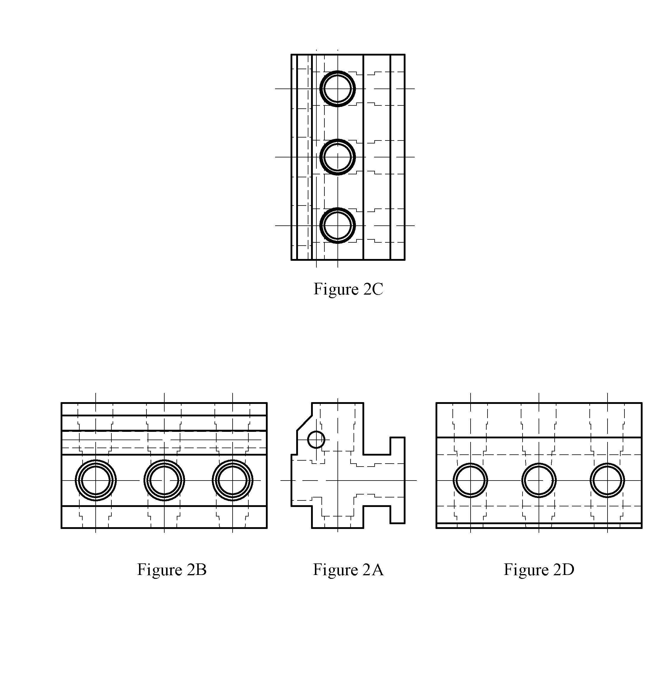
[0051]FIG. 7A illustrates an embodiment of a cross-section of a fluid end housing 12 ...
PUM
 Abstract
Description
Claims
Application Information