Electric connector
a technology of electrical connectors and glow plugs, applied in the direction of coupling devices, two-part coupling devices, electrical apparatus, etc., can solve the problems of deteriorating reliability of electrical connection between glow plugs and female connectors, and achieve the effect of improving reliability of electrical connection
- Summary
- Abstract
- Description
- Claims
- Application Information
AI Technical Summary
Benefits of technology
Problems solved by technology
Method used
Image
Examples
first embodiment
[0059]The electric connector in accordance with the first embodiment of the present invention will be explained hereinbelow with reference to the drawings.
[0060]In the specification, “front” or “distal” means a portion of a connector through which the connector is fit into a corresponding connector, and “rear” or “proximal” means an opposite portion of the connector.
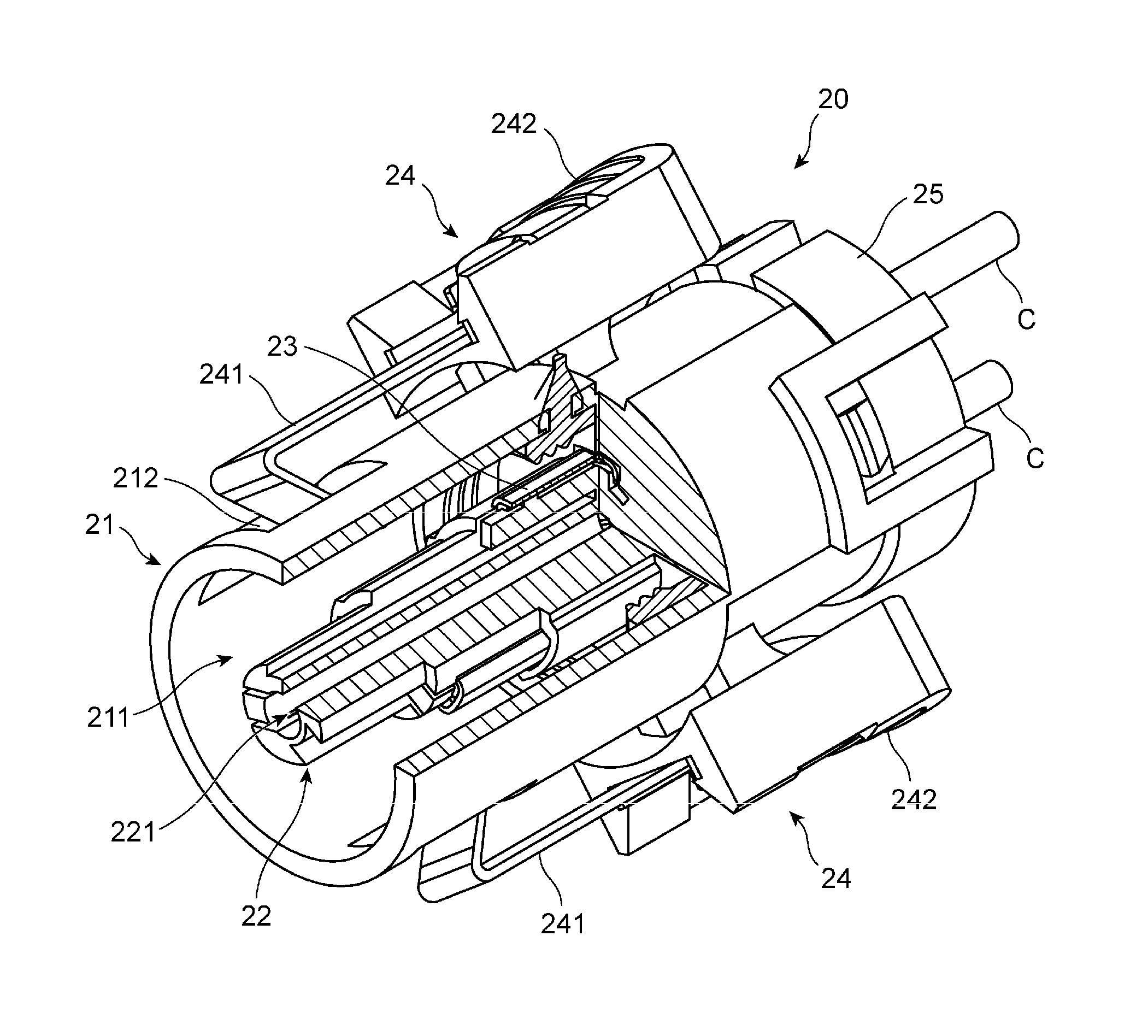
[0061]The electric connector in accordance with the first embodiment is designed to include a male connector 10 and a female connector 20.
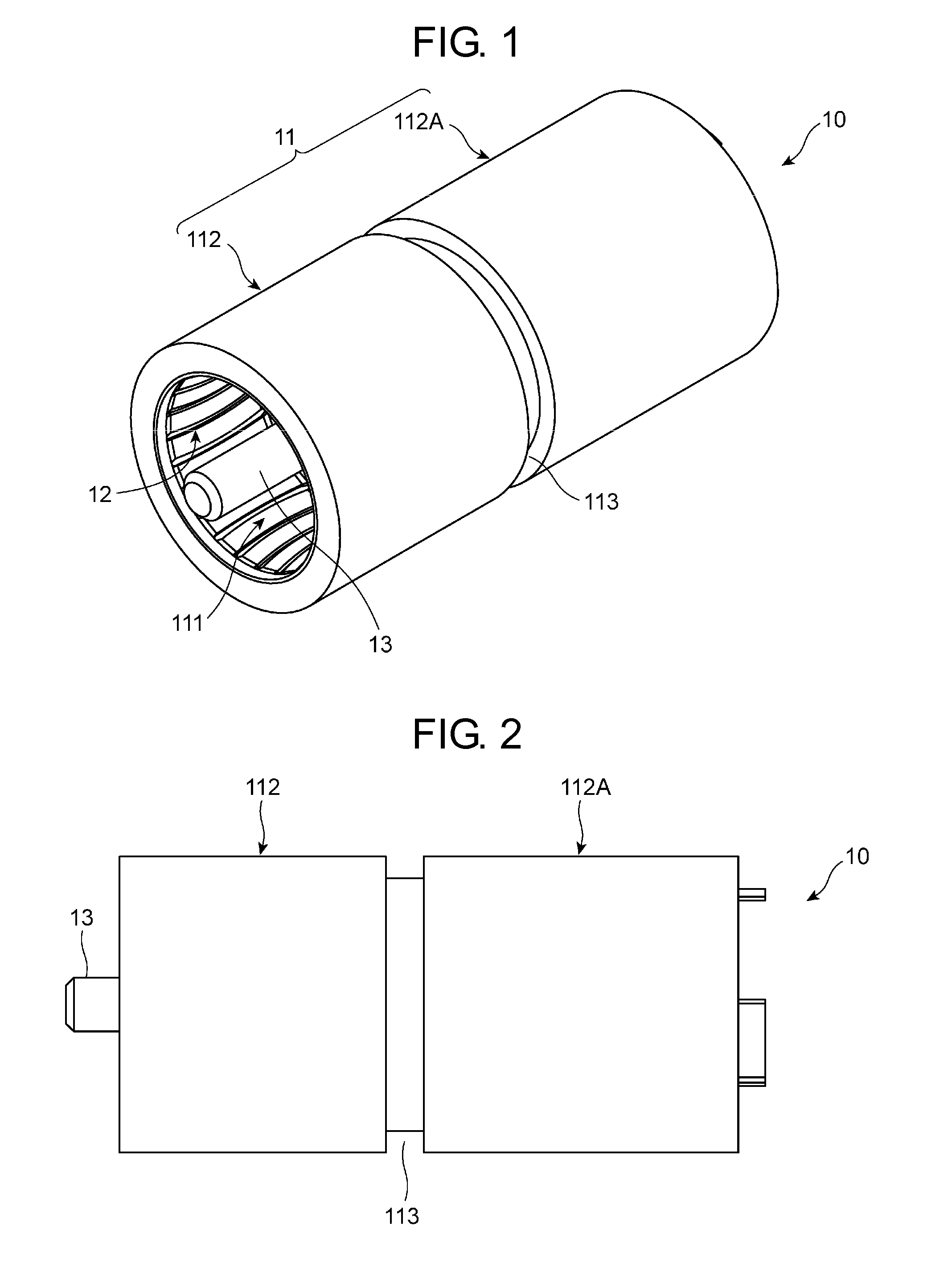
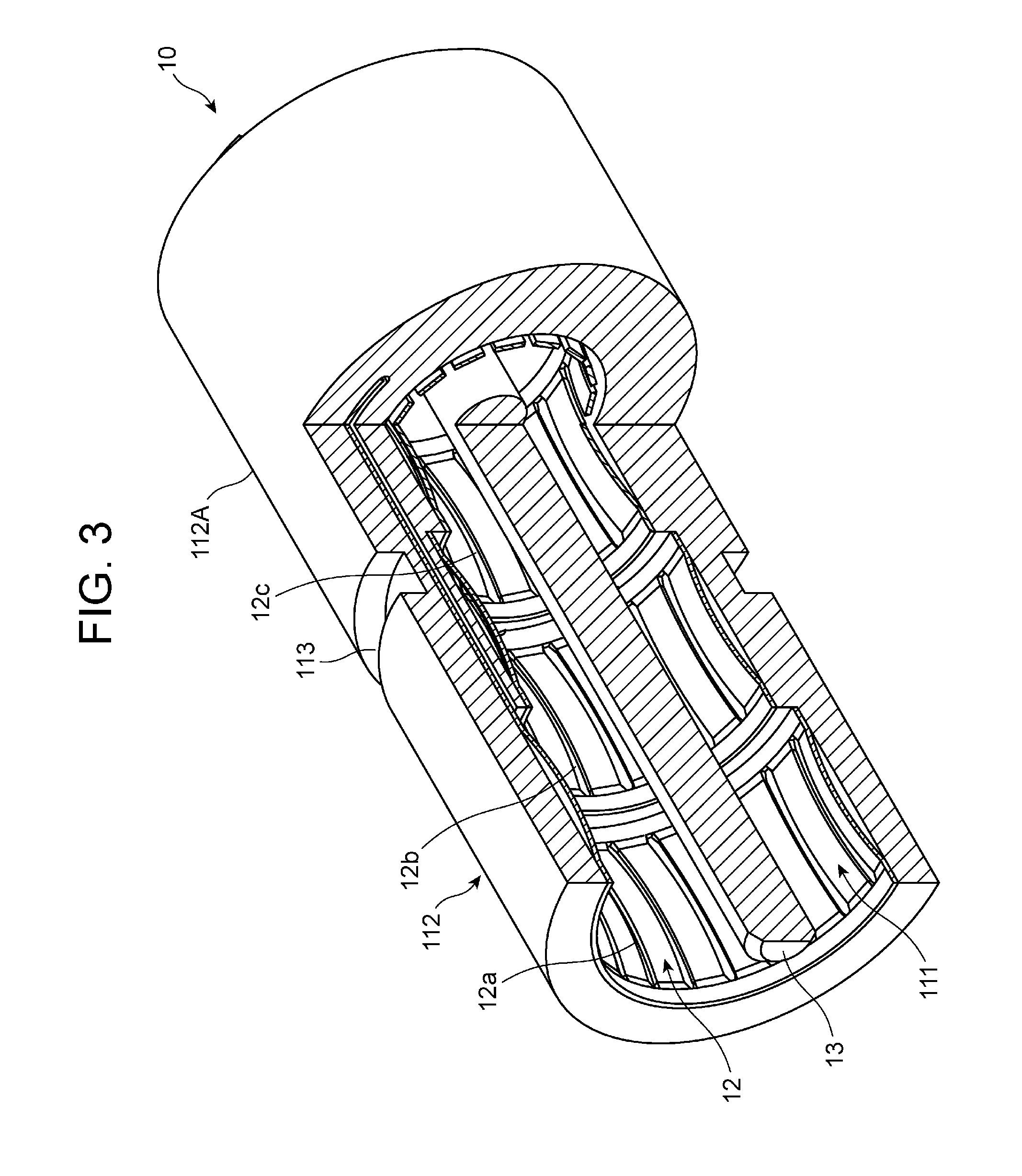
[0062]The male connector 10 illustrated in FIGS. 1 to 3 includes a housing 11 as a main body of the connector, a male contact terminal 12 formed on an inner surface of the housing 11, and a guide shaft 13 formed in a hole 111 of the housing 11 and extending beyond an opening end of the housing 11 in a direction in which the male connector 10 is fit into the female connector 20.
[0063]The housing 11 is in the form of a cylinder having an opening end and a bottom. An inner surface of the ...
second embodiment
[0092]The electric connector in accordance with the second embodiment of the present invention is explained hereinbelow with reference to the drawings. Parts or elements in FIGS. 18 to 20 that correspond to those of the first embodiment illustrated in FIGS. 1 to 17 have been provided with the same reference numerals, and are not explained.
[0093]As detailed later, the electric connector in accordance with the second embodiment is characterized in that a male connector 10X is designed to include projections 116, and a female connector 20X is designed to include an engagement section 24X making engagement with the projections 116 to thereby prevent the male connector 10X from rotating about an axis thereof.
[0094]As illustrated in FIG. 18, the male connector 10X in the second embodiment is designed to include a housing 11X having a first portion 112X and a second portion 112AX adjacent to the first portion 112X. The first portion 112X has a circular cross-section, and has a cylindrical ...
third embodiment
[0099]The electric connector in accordance with the third embodiment of the present invention is explained hereinbelow with reference to the drawings. Parts or elements in FIGS. 21 and 22 that correspond to those of the first and second embodiments illustrated in FIGS. 1 to 20 have been provided with the same reference numerals, and are not explained.
[0100]As mentioned later in detail, the male connector in the third embodiment is characterized in that the guide shaft is designed to include a first cylindrical portion and a second portion including a plurality of projections, and the guide hole is formed at an inner surface thereof with grooves making engagement with the projections to thereby prevent the male connector from rotating about an axis thereof.
[0101]As illustrated in FIG. 21, a male connector 10Y in the third embodiment includes a guide shaft 13Y. The guide shaft 13Y is designed to include a first portion 13a and a second portion 13b. The first portion 13a has a circular...
PUM
 Abstract
Description
Claims
Application Information
 - R&D
- Intellectual Property
- Life Sciences
- Materials
- Tech Scout
- Unparalleled Data Quality
- Higher Quality Content
- 60% Fewer Hallucinations
Browse by: Latest US Patents, China's latest patents, Technical Efficacy Thesaurus, Application Domain, Technology Topic, Popular Technical Reports.
© 2025 PatSnap. All rights reserved.Legal|Privacy policy|Modern Slavery Act Transparency Statement|Sitemap|About US| Contact US: help@patsnap.com


