Arrangement of coil wires in a rotor of an electric motor

a technology of electric motor and rotor, which is applied in the direction of dynamo-electric machines, electrical apparatus, magnetic circuits, etc., can solve the problems of difficult to wind coils on teeth orally, uncontrolled wire crossing, and inability to precisely determine the position of coil wires and coils, so as to reduce the resistance of coils and improve the efficiency of motors

Active Publication Date: 2016-09-06
NIDEC MOTORS & ACTUATORS GERMANY
View PDF14 Cites 2 Cited by
  • Summary
  • Abstract
  • Description
  • Claims
  • Application Information

AI Technical Summary

Benefits of technology

[0008]The switching wire receptor in the cavity or between the teeth may be used to place, guide and / or support the switching wire in a predetermined position. This allows placing the switching wires as well as the coil wires more precisely which reduces unbalanced mass of the armature and manufacturing of the coils and the armature is made easier. It is also possible to construct coils and armatures without crossing wires as the switching wires are arranged separately in the switching wire receptor which allows reducing the size, i.e. the radius of the armature. The invention helps in designing smaller and more lightweight motors.
[0013]The placing of the at least one switching wire in the switching wire receptor arranged in the cavity of the armature may be performed prior to or after the winding the coil wires on the coil guiding surface of the at least one cavity. The final position of the coil wires remains the same in both cases, i.e. the order of manufacturing has no influence on the position of the coil wires on the teeth and in the cavities, which makes coils formed with the coil wires wound orderly on the teeth. And orderly wound coil wires can reduce the resistance of the coils, which improves the efficiency of the motor.

Problems solved by technology

This has the disadvantage that the position of the coil wires and the coil cannot be determined precisely and manufacturing sequence has to be considered.
If the manufacturing sequence was not considered, in some cavities the switching wires will be arranged at the positions where coils are supposed to be arranged, so it is difficult to wind coils on teeth orderly, which will have several negative effects like uncontrolled wire crossings, increased end turn height, unbalance and efficiency degradation of motor.

Method used


Image

  • Arrangement of coil wires in a rotor of an electric motor
  • Arrangement of coil wires in a rotor of an electric motor
  • Arrangement of coil wires in a rotor of an electric motor

Examples


Embodiment Construction

[0020]Examples of the present disclosure are now described in more detail. It is to be noted that not all features of these examples need to be implemented to carry out the invention and that a person skilled in the art will modify, add or omit features depending on the application of the armature and the electric motor.

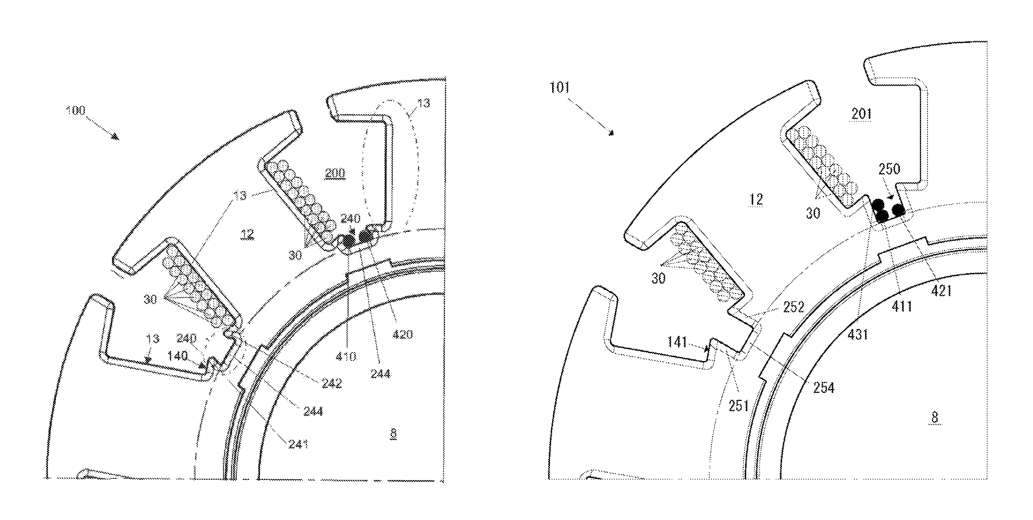
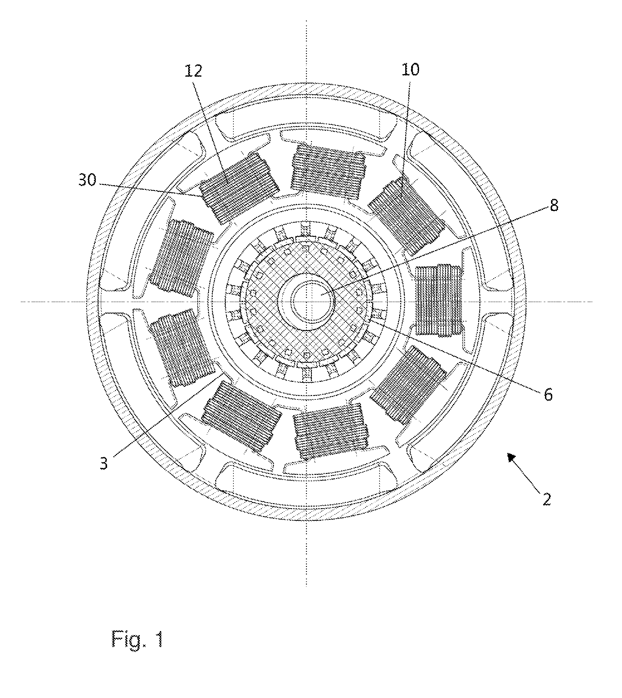
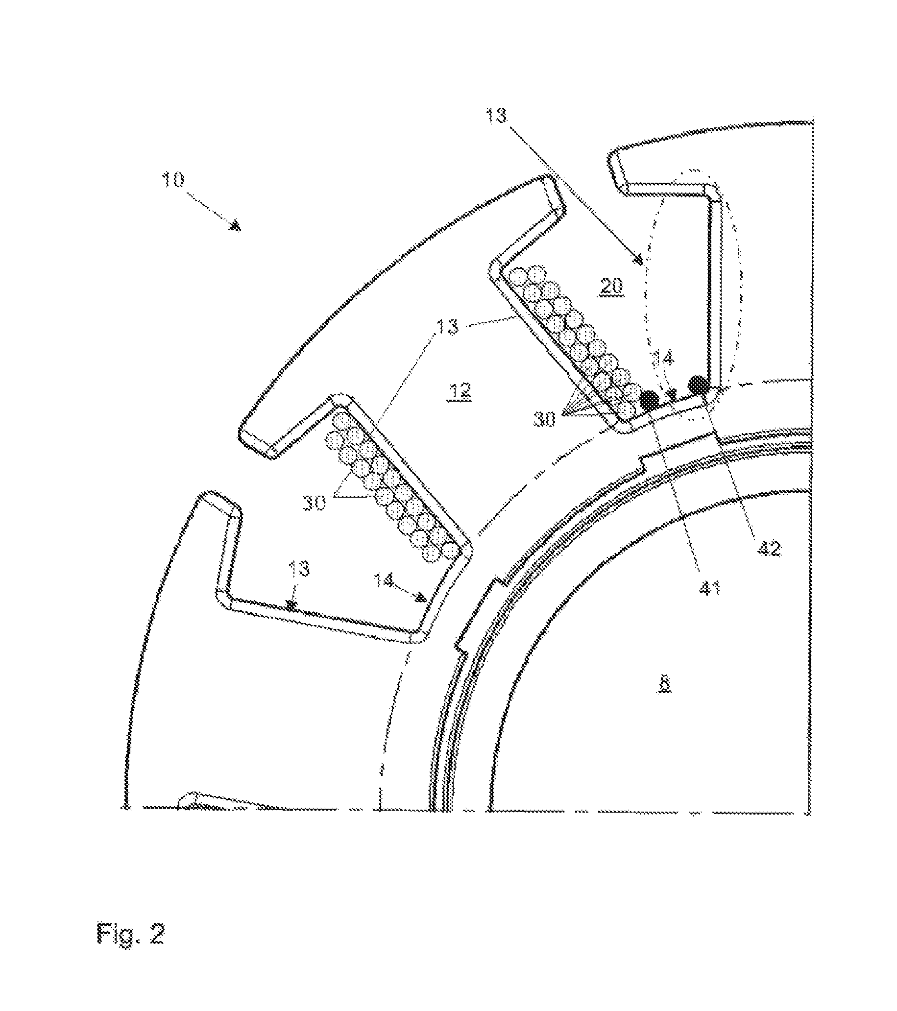
[0021]FIG. 1 shows an electric motor 2 in which the present invention may be implemented. The electric motor may be a conventional electric motor and comprises a rotor 3 with an armature 10 arranged on a rotating shaft 8. A commutator 6 with a plurality of contact elements also placed on the rotating shaft 8 in a usual manner. The armature 10 comprises a plurality of teeth 12 that are arranged around the rotational axis of the shaft 8. The teeth 12 may have a mushroom like shape and may be made from a magnetisable material as known in the art. All parts of the electric motor that are not specifically mentioned herein may be as in any electric motor known in the art.

[...


PUM

PropertyMeasurementUnit
diameteraaaaaaaaaa
magnetizationaaaaaaaaaa
electricallyaaaaaaaaaa

Abstract

An armature for an electric motor, the armature comprising a plurality of teeth and a plurality of cavities, wherein each one of the cavities is arranged between two of the plurality of teeth, and wherein at least one of the plurality of cavities is configured and arranged for receiving coil windings adjacent to a wall portion of the at least one cavity, wherein the at least one of the plurality of cavities comprises a switching wire receptor.

Description

BACKGROUND OF THE INVENTION[0001]1. Field of the Invention[0002]The present disclosure relates to electric motors. The present disclosure relates in particular to armatures for electric motors and to the arrangement of switching wires and of coil wires on the armature.[0003]2. Brief Description of the Related Art[0004]Armatures of brushed electric motors comprise coils wound around the teeth of the armature for providing the required magnetization of the teeth of the armature. Magnetisation of the teeth is done by applying an electric current through the coil. The coils are electrically contacted via brushes and a commutator in a general known manner. While an electric motor has at least two coils and two teeth, modern electric motors have a plurality of teeth such as for example four or more teeth. A coil is wound around each tooth or a plurality of teeth and individually addressed via the commutator.[0005]While the armature may be seen as having a plurality of teeth arranged aroun...

Claims


Application Information

Patent Timeline
Patent Type & Authority Patents(United States)
IPC IPC(8): H02K1/14H02K13/04H02K15/00H02K3/12
CPCH02K3/12H02K13/04H02K15/0031Y10T29/49009H02K1/165H02K1/265H02K3/28H02K3/325H02K23/00H02K23/30H02K1/22H02K3/46
Inventor SCHMID, JUERGEN
Owner NIDEC MOTORS & ACTUATORS GERMANY
Why Eureka
Try Eureka