Mass balancing mechanism

A technology of mass balance and transmission mechanism, which is applied in the direction of engine components, mechanical equipment, vibration suppression adjustment, etc., can solve the problems of high friction power, loss, etc., and achieve the effect of sufficient lubrication and/or cooling

Inactive Publication Date: 2011-03-30
SCHAEFFLER TECH AG & CO KG
View PDF9 Cites 4 Cited by
  • Summary
  • Abstract
  • Description
  • Claims
  • Application Information

AI Technical Summary

Problems solved by technology

However, it is known that sliding bearings produce significantly higher frictional power losses than r

Method used


Image

  • Mass balancing mechanism
  • Mass balancing mechanism
  • Mass balancing mechanism

Examples


Embodiment Construction

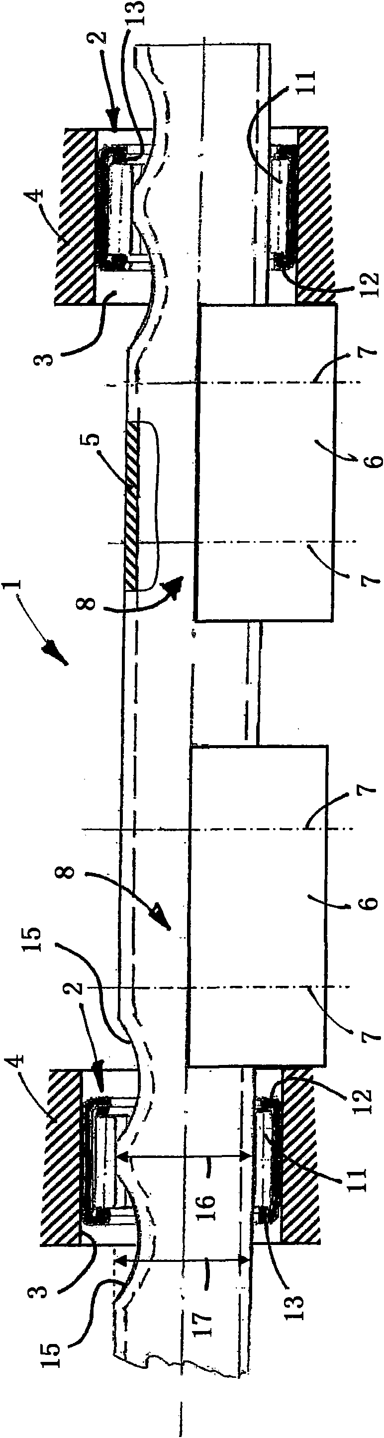
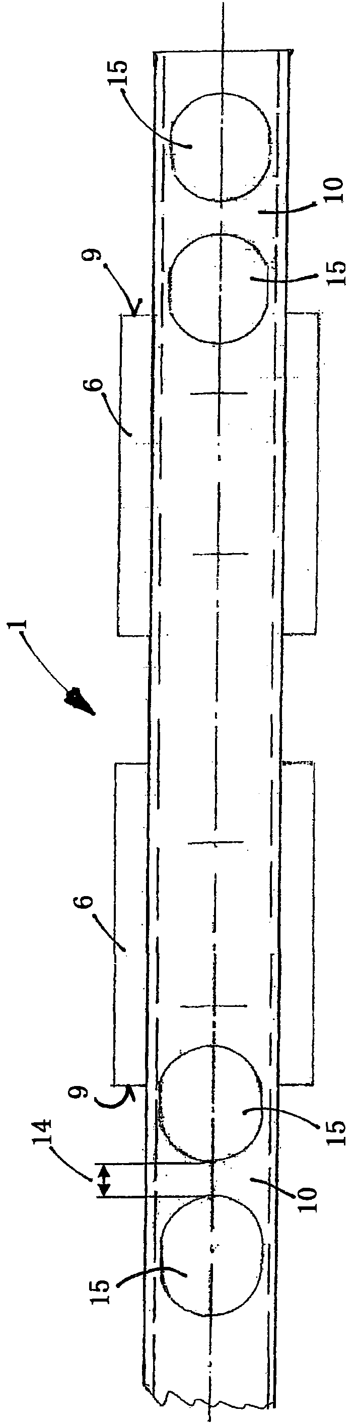
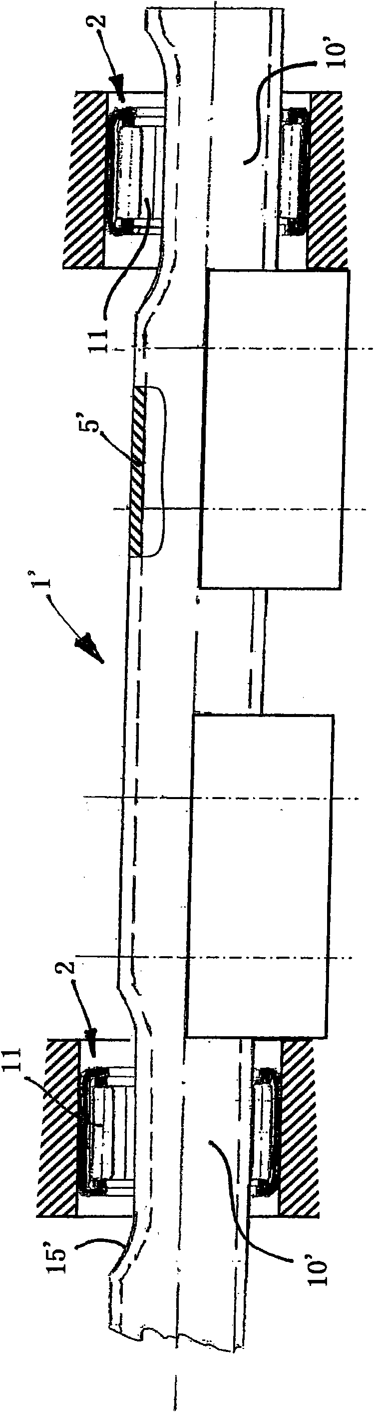
[0016] exist figure 1 and figure 2 Shown in side view or in top view is one of two counter-rotating balance shafts 1 at double the crankshaft speed, which engages with needle bearings 2 to form part of a mass balance transmission for balancing the second stage of an internal combustion engine free inertia force. The balancing shaft 1 accommodated in radial rolling bearing in the bearing housing 3 of the undivided housing 4 of the internal combustion engine consists of a bearing shaft 5 and two unbalanced masses 6 which are screwed to the bearing shaft 5 here by means of screws Combined, wherein, the support shaft 5 is made of a precision tube made of rolling bearing steel. The screw-in points 7 are shown. The screwing of the unbalanced mass 6 onto the matching connecting section 8 of the bearing shaft 5 takes place after the bearing shaft 5 has been pushed into the bearing seat 3 because the diameter of the enveloping circle of the unbalanced mass 6 is larger than Housing...


PUM


Abstract

A mass balancing mechanism of an internal combustion engine, in which the mechanism includes a compensation shaft formed as a tubular carrier shaft having a mounting point for the radial mounting of the compensation shaft. The mechanism further includes an unbalanced mass joined to the carrier shaft. A needle roller bearing is used for a radial rolling bearing-mounting of the compensation shaft, with the needle rollers of the needle roller bearing being in rolling contact with the mounting point which is configured as an inner raceway and possesses a width which is variable in peripheral direction, so that, in a region situated diametrically opposite a load zone in whose peripheral region the inner raceway is loaded by the radial load of the unbalanced mass which rotates together with the compensation shaft, a width of the inner raceway is smaller than the length of the needle rollers and tapers clearly or is interrupted in peripheral direction. The tapering or interruption of the inner raceway is produced by one or more trough-shaped depressions formed locally in the carrier shaft.

Description

technical field [0001] The invention relates to a mass-balance transmission for balancing the inertial forces and / or moments of inertia of an internal combustion engine. The mass balance transmission comprises a balance shaft having a tubular bearing shaft with bearing points (Lagerstelle) formed on its outer circumference for radially supporting the balance shaft in the internal combustion engine; A connected unbalanced mass engages the bearing shaft at a connection section of the bearing shaft running laterally at the bearing point. Background technique [0002] This mass-balanced transmission comes from the article "Derneue 1.8-I-Vierzylinder-Ottomotor von Mercedes-Benz (the new 1.8- I four-cylinder gasoline engine)". The balanced drive gearbox consists of two counter-rotating balance shafts at double the crankshaft speed to balance the second order free inertial forces. In the case of a designed balancing shaft with a tubular bearing shaft, the balancing shaft is inse...

Claims


Application Information

Patent Timeline
IPC IPC(8): F16F15/26F16C19/22F16C33/58
CPCF16F15/268F16F15/267F16C19/466F16C33/585F16C2361/53Y10T74/2183
Inventor 西格弗里德·蒂施
Owner SCHAEFFLER TECH AG & CO KG
Why Eureka
Try Eureka