
Supporting element for pipes in buildings and application method of a pipe supporting element in a flagstone

a technology of supporting elements and pipes, applied in the field of tubing support, can solve the problems of slab molds that are impaired by frequent fixation and removal of wood crates, lack of dimensional precision in positioning the tubing, and inconvenient to use, so as to prevent failures

Active Publication Date: 2016-09-13
VICENTE DE AZEVEDO EBOLI MARIA ISABEL
View PDF15 Cites 2 Cited by
  • Summary
  • Abstract
  • Description
  • Claims
  • Application Information

AI Technical Summary

Benefits of technology

[0016]The present invention has the objective of achieving a prefabricated tubing support, which reduces the costs and time for carrying out the installation of tubing in building construction works.
[0019]The present invention has also the objective of providing a process for installing tubing that is capable of aiding in standardization of the positioning of tubes inside a construction, thus preventing failures due to inaccuracy in positioning the tubing.
[0020]Finally, the present invention further has the objective of providing a process of installing tubing that will not damage the slab mold with the successive fixation and removal of wooden boxes.

Problems solved by technology

It should be noted that this process (just as the first one, described in the beginning of this specification), is time consuming and expensive.
It should be noted that, besides consuming time and money, this process may bring other drawbacks, as will be disclosed hereinafter.
The wooden crate employed to form the rectangular spacing is generally fixed with nails onto the slab-mold floor and, in relatively high buildings, the slab mold is impaired by frequent fixation and removal of the wood crates.
Another drawback is the lack of dimensional precision in positioning the tubing, which is inherent in employing this process.
It is known that this process may entail variation in the positioning of the tubes with respect to the slab, which, as a result, may alter the positioning of the tubing on a determined building floor.
A third problem, besides the high cost and long time for carrying out this process, is that the concrete used for filling the space between the slab and the tubing, after having hardened in its curing process, leads to sound vibrations and thermal energy from the tubing to the slab and to the environment adjacent the slab.
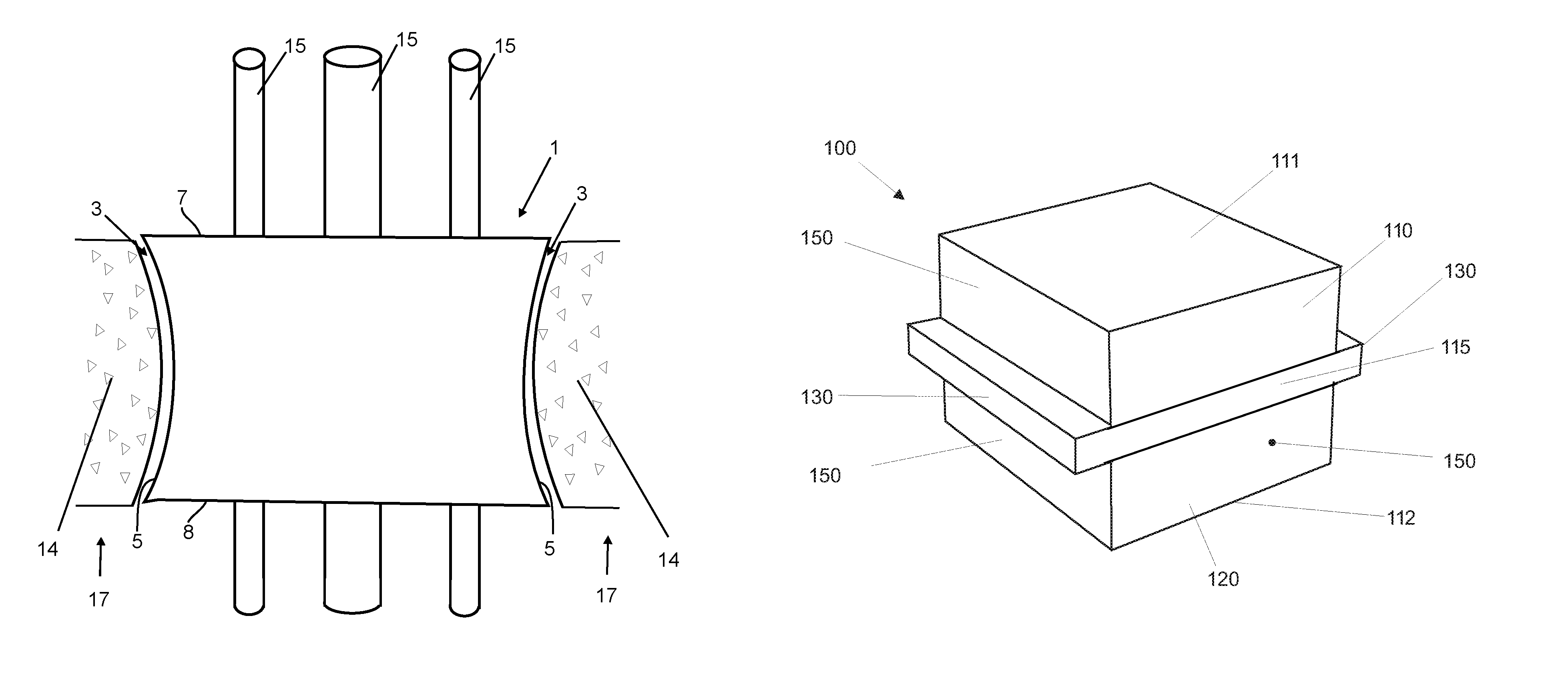
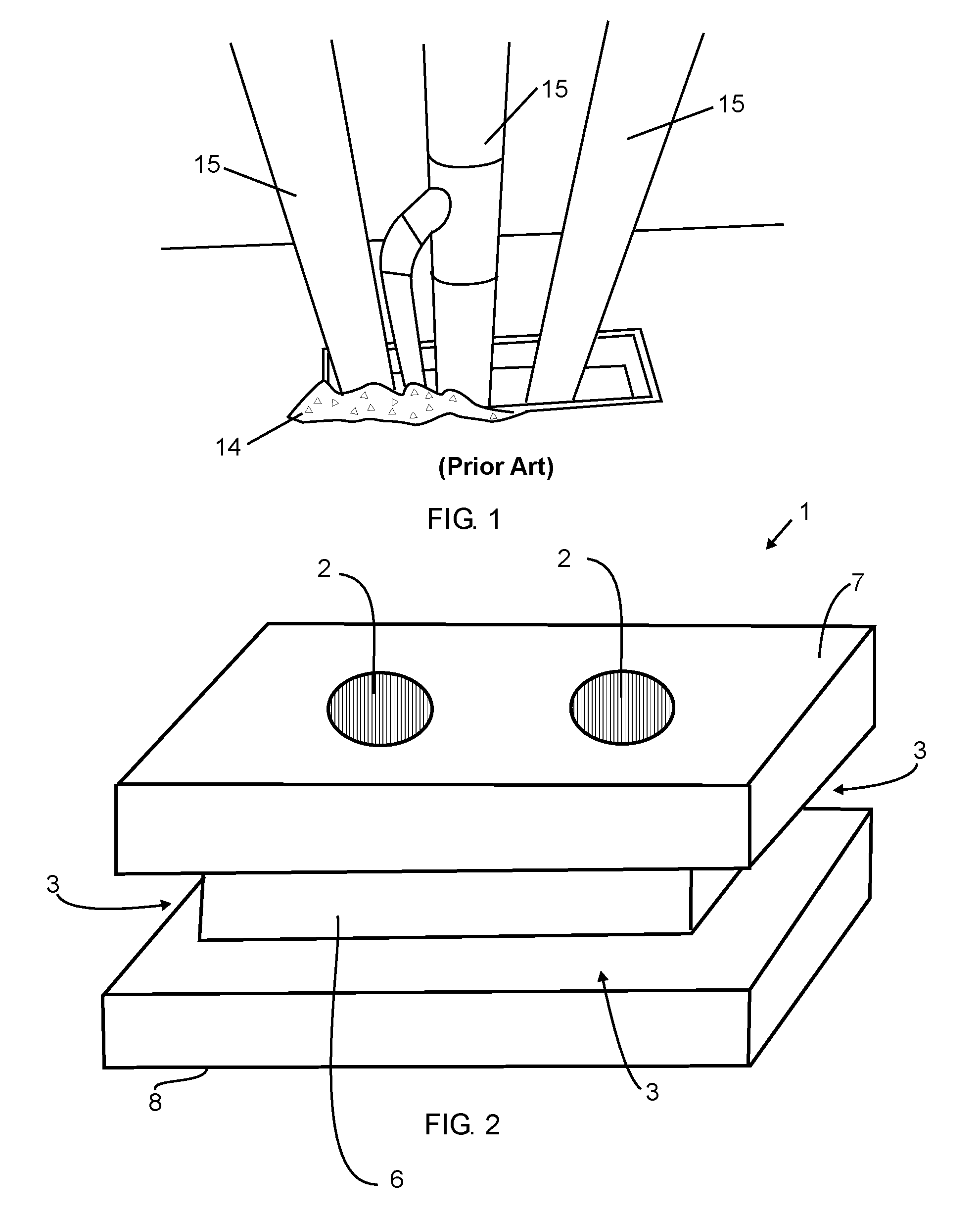
Additionally, such prior-art procedures generate debris and slowness in developing the work due to the need for a complementary step for concreting (see FIG. 1).
Therefore, one concludes that the technical solutions employed at present in tubing installations—perforation of existing dividers and the process that makes use of fixing wooden boxes onto the slab molds before concreting=cause great drawbacks before, during and after the carrying-out thereof.

Method used


Image

  • Supporting element for pipes in buildings and application method of a pipe supporting element in a flagstone
  • Supporting element for pipes in buildings and application method of a pipe supporting element in a flagstone
  • Supporting element for pipes in buildings and application method of a pipe supporting element in a flagstone

Examples


Embodiment Construction

[0070]Various example embodiments of the present invention will now be described more fully hereinafter with reference to the accompanying drawings, in which some, but not all embodiments of the invention are shown. Indeed, embodiments of the invention may be embodied in many different forms and should not be construed as limited to the embodiments set forth herein. Rather, these embodiments are provided so that this disclosure will satisfy applicable legal requirements. Unless otherwise defined, all technical and scientific terms used herein have the same meaning as commonly known and understood by one of ordinary skill in the art to which the invention relates. The term “or” is used herein in both the alternative and conjunctive sense, unless otherwise indicated. Like numbers refer to like elements throughout.

[0071]To facilitate the understanding of this invention, a number of terms are defined below. Terms defined herein have meanings as commonly understood by a person of ordinar...


PUM


Abstract

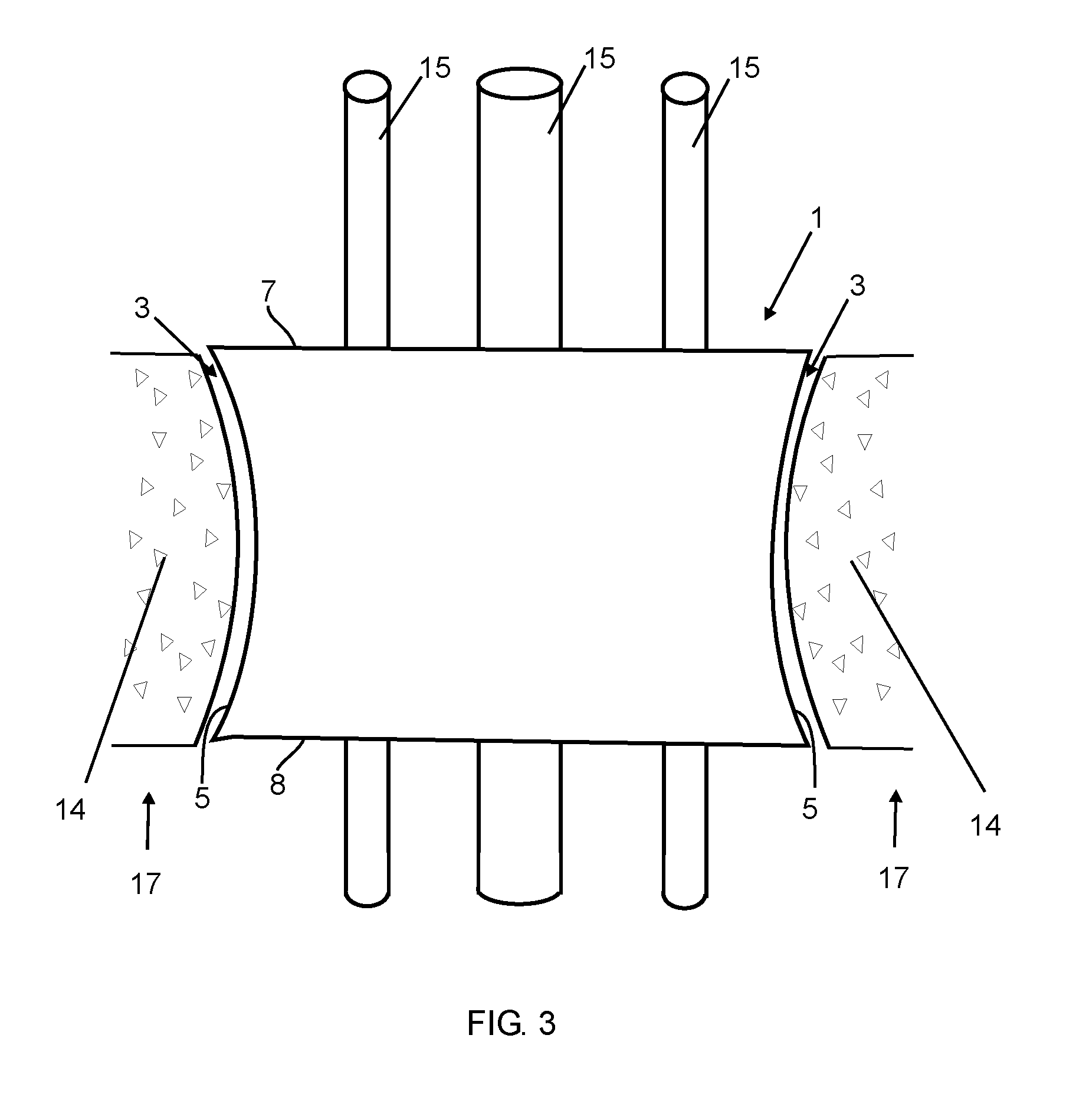
This relates to a pipe supporting element (1) used to contain a pipe (15) that is used in buildings for hydraulic, electrical and other pipes. In one preferred arrangement, the aforementioned pipe supporting element comprises polyethylene foam, is as thick as a partition (wall or paving slab), has at least two anchoring points located on the side faces (3) thereof, and includes at least one through hole (2) between a first face (1) and a second face (2).

Description

CROSS-REFERENCE TO RELATED APPLICATIONS[0001]This application claims priority to and the benefit of U.S. patent application Ser. No. 14 / 353,603, filed Apr. 23, 2014, which United States Patent Application is a National Stage Application, filed under 35 U.S.C. §371, of International Application No. PCT / BR2012 / 000417, filed Oct. 29, 2012, which International Application claims priority to and the benefit of Brazilian Application No. PI1106760-8, filed Oct. 28, 2011; the contents of all of which are hereby incorporated by reference in their entirety.BACKGROUND[0002]1. Technical Field[0003]The present invention relates to a tubing support for application in buildings, application on dividers such as partition walls and slabs, configured to accommodate water tubing, electricity and gas lines in a stable position on divider.[0004]2. Related Art[0005]Upon carrying out works in the field of civil construction, there are steps that consist in installing tubing pieces, which are designed to c...

Claims


Application Information

Patent Timeline
Patent Type & Authority Patents(United States)
IPC IPC(8): E04C2/52E04B5/48F16L5/14H02G3/22E04B5/36E04G15/00F16L5/10
CPCE04B5/48E04B5/36E04G15/00F16L5/10F16L5/14H02G3/22E04G15/061
Inventor DE FREITAS SILVESTRE, WLADIMIR
Owner VICENTE DE AZEVEDO EBOLI MARIA ISABEL
Learn More