Core winding method and stator

a winding method and stator technology, applied in windings, electrical devices, dynamo-electric machines, etc., can solve the problems of difficult winding of conductive wires on the core with a high occupancy, the tip of the nozzle cannot be made to approach a tooth portion, and the winding cannot be placed with a high positional accuracy, etc., to suppress the facility cost of winding and increase the number of turns

Active Publication Date: 2016-09-13
MITSUBISHI ELECTRIC CORP
View PDF19 Cites 0 Cited by
  • Summary
  • Abstract
  • Description
  • Claims
  • Application Information

AI Technical Summary

Benefits of technology

[0014]According to the present invention, a conductive wire can be wound in an aligned manner in a bow-like area of a core having an arch-like yoke portion by using a general-purpose winding machine that moves a nozzle in x axis, y axis, z axis directions orthogonal to each other. Therefore, it becomes possible to increase the number of turns of the conductive winding and the occupancy of the conductive winding, and suppress the facility cost for winding.

Problems solved by technology

In a normal core winding method, upon winding in the bow-like area surrounded by the arc of the inner circumference of the arch-like yoke portion and the chord of the arc, since a nozzle interferes with the yoke portion, the tip of the nozzle cannot be made to approach a tooth portion, and as a result, the winding cannot be placed with a high positional accuracy.
Therefore, it is difficult to wind the conductive wire on the core with a high occupancy.

Method used


Image

  • Core winding method and stator
  • Core winding method and stator
  • Core winding method and stator

Examples


embodiment 1

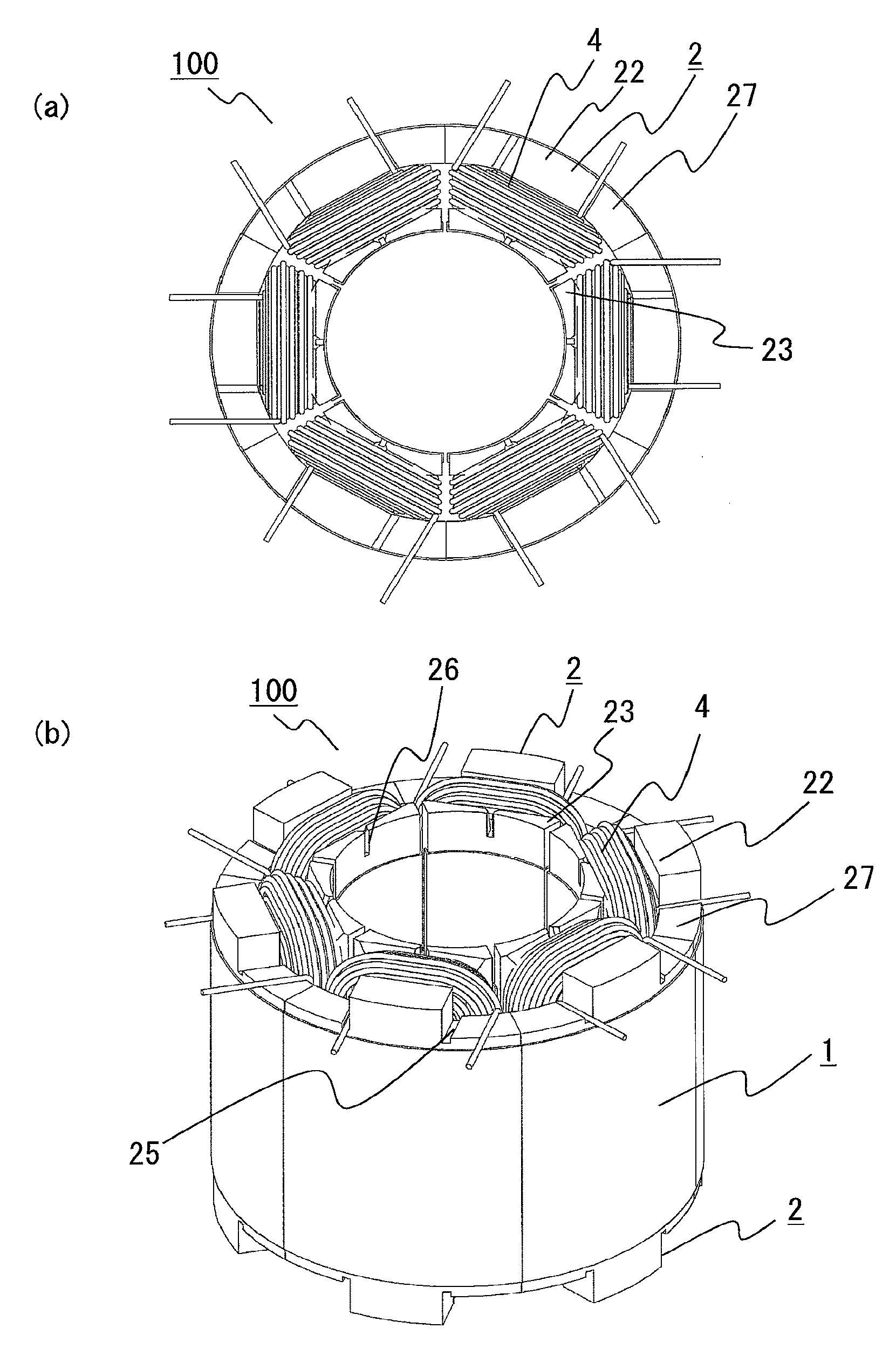
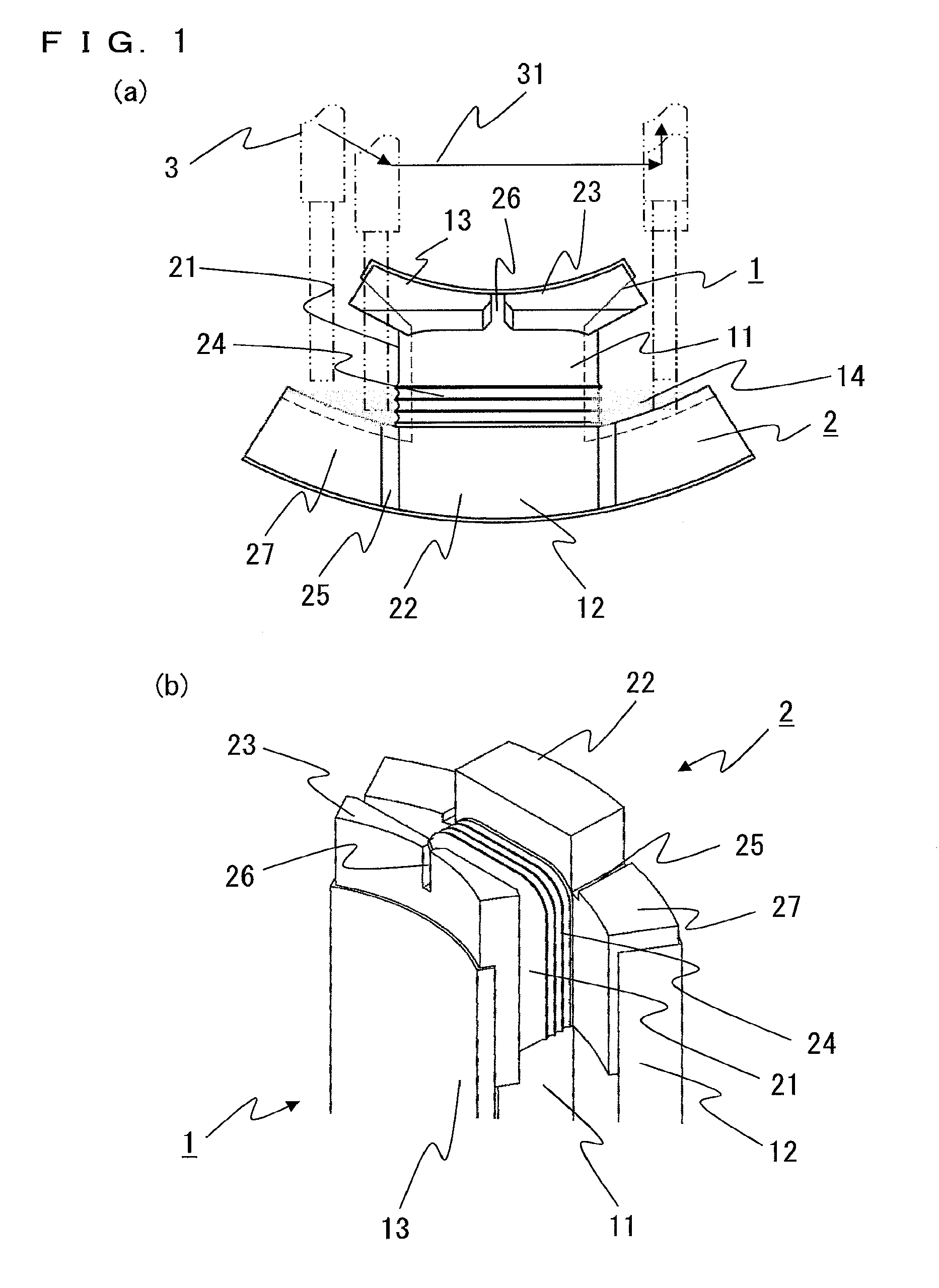
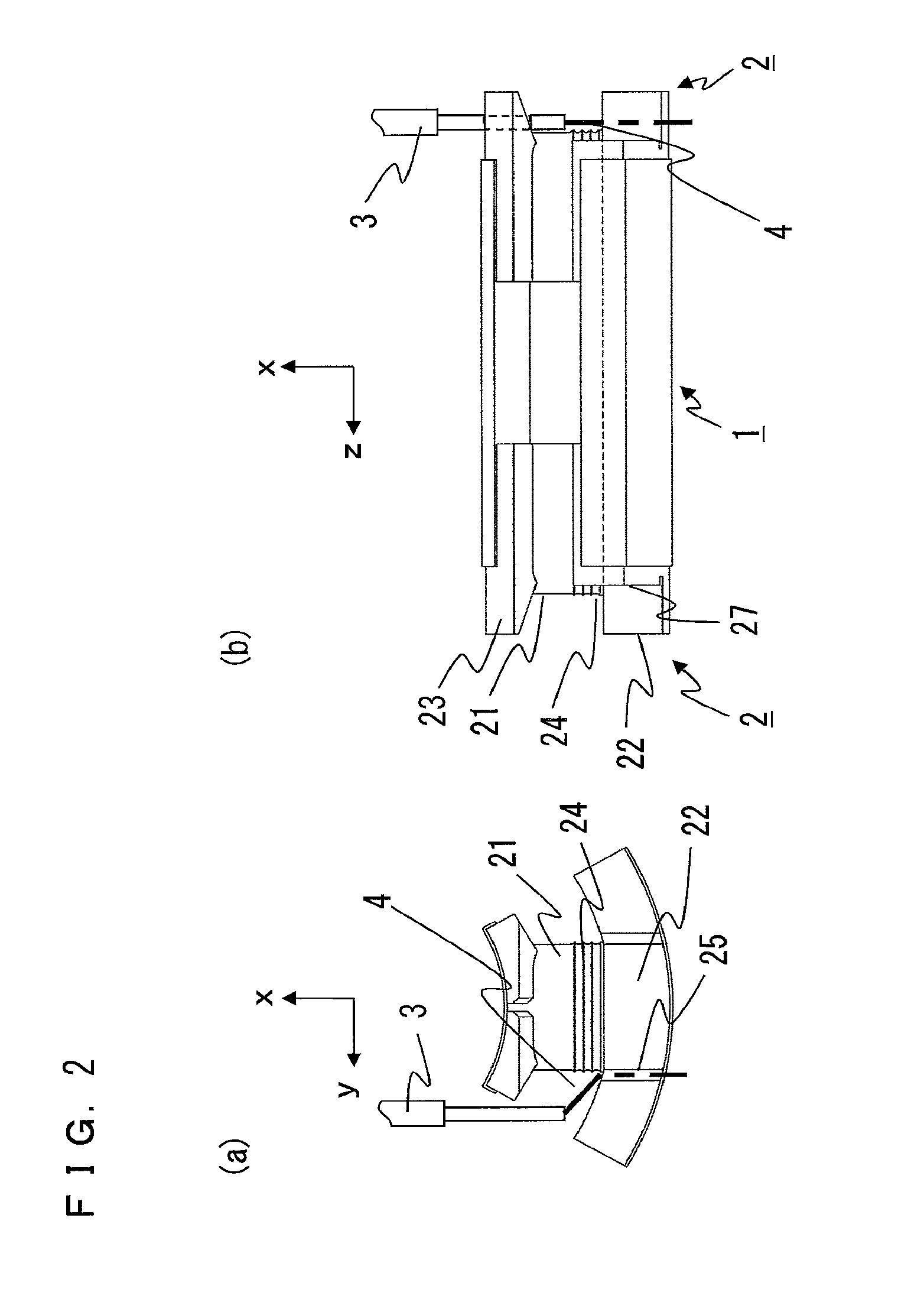
[0028]FIGS. 1(a) and 1(b) are a front view and a perspective view showing the shapes of a divided-type core and an insulator according to an embodiment of the present invention. FIGS. 2 to 8 are diagrams for explaining a core winding method according to embodiment 1 of the present invention.

[0029]A divided-type core 1 is formed by punching silicon steel plates or the like in the same shape by using a press mold and then laminating a plurality of the punched steel plates. Welding, bonding, swaging, or the like is used as means for fixing the laminated steel plates. The divided-type core 1 has: an arch-like yoke portion 12 having a radially outward convex shape; a tooth portion 11 protruding radially inward from the center portion of the yoke portion 12 and to be wound with a conductive wire 4; and a tooth end portion 13 connected to the end of the tooth portion 11. The yoke portions 12 of a plurality of the divided-type cores 1 are combined in a circular shape, to form a stator.

[0030...

embodiment 2

[0052]FIGS. 10 to 13 are diagrams explaining a core winding method according to embodiment 2 of the present invention. In embodiment 1, winding is started from the base portion side of the insulator. In the present embodiment, the case of starting winding from the winding frame end portion side of the insulator will be described. It is noted that the structures of the divided-type iron core and the insulator are the same as those of embodiment 1, and therefore the description thereof is omitted.

[0053]First, an end portion of the conductive wire 4 fed from the nozzle 3 is passed through the winding frame end portion side guide groove 26 of the insulator 2, and then the end portion of the conductive wire 4 is held by a chuck device not shown.

[0054]Then, the nozzle 3 is revolved along the end surface and the side surface of the divided-type core 1, whereby the conductive wire 4 is wound on the winding frame portion 21 of the insulator 2 from the winding frame end portion side to the ba...


PUM

PropertyMeasurementUnit
conductiveaaaaaaaaaa
circumferenceaaaaaaaaaa
areaaaaaaaaaaa

Abstract

In a method for winding a core having an arch-like yoke portion, a tooth portion, and a tooth end portion by revolving a nozzle for feeding a conductive wire, when winding is performed in a bow-like area surrounded by an inner circumferential arc of the yoke portion and the chord thereof, upon winding on an end surface of the core, the nozzle moves so as to draw a convex-shaped trajectory proceeding from the tooth end portion side toward the yoke portion side with reference to the chord of the bow-like area, and upon winding on a side surface of the core, the nozzle returns from the yoke portion side to the tooth end portion side with reference to the chord of the bow-like area, and then moves along the side surface of the core.

Description

TECHNICAL FIELD[0001]The present invention relates to a core winding method for winding a conductive wire on a core having an arch-like yoke portion and a tooth portion protruding radially inward from the center portion of the yoke portion, and to a stator manufactured by the core winding method.BACKGROUND ART[0002]In order to increase the number of turns of a conductive winding, a yoke portion of a core may be formed in an arch-like shape and a conductive wire may be wound in a bow-like area surrounded by an arc of the inner circumference of the yoke portion and a chord connecting both ends of the arc, thereby increasing the area for storing the conductive winding.[0003]In a normal core winding method, upon winding in the bow-like area surrounded by the arc of the inner circumference of the arch-like yoke portion and the chord of the arc, since a nozzle interferes with the yoke portion, the tip of the nozzle cannot be made to approach a tooth portion, and as a result, the winding c...

Claims


Application Information

Patent Timeline
Patent Type & Authority Patents(United States)
IPC IPC(8): H02K1/00H02K3/46H02K15/095H02K15/04H02K3/52H02K15/00
CPCH02K3/46H02K3/522H02K15/0435H02K15/095H02K15/0081H02K2203/12Y10T29/49009
Inventor SHIJO, DAISUKETANAKA, TAKAHIROAKITA, HIROYUKI
Owner MITSUBISHI ELECTRIC CORP
Why Eureka
Try Eureka