Steam turbine power plant

a steam turbine and power plant technology, applied in steam engine plants, wind motors with perpendicular air flow, machines/engines, etc., can solve the problems of increasing facility costs, increasing facility costs, and thermal stress, so as to improve thermal efficiency and ensure economic efficiency.

Active Publication Date: 2005-02-03
KK TOSHIBA
View PDF4 Cites 24 Cited by
  • Summary
  • Abstract
  • Description
  • Claims
  • Application Information

AI Technical Summary

Benefits of technology

According to this steam turbine power plant, the intermediate-pressure turbine is provided with the steam cooling unit for cooling the rotor by the cooling steam. Therefore, the rotor can be formed of the same ferritic alloy steels as before and the thermal efficiency can be improved even if the high-temperature steam of 650° C. or more is introduced into the intermediate-pressure turbine and the economical efficiency can be assured. The alloy steel described in 39) above is used for the steam turbine and has a property that the metallic compounds of the M23C6 type carbide, M2X type carbonitride and MX type carbonitride precipitate during its operation, and the total of precipitates initially contained is 2.0 to 4.0% by weight but a total of precipitates becomes 4.0 to 6.0% by weight after the alloy steel is used for the high-temperature, intermediate-pressure turbine. And, the desired mechanical properties can be obtained because this alloy steel is configured in such a manner that the specified types of precipitates, metallographical precipitated positions and their precipitated amounts and component element ratio are satisfied.

Problems solved by technology

But, there were problems that the use of the austenitic heat-resistant steels increased the facility cost, and a thermal stress tended to occur at a time of change in load when the plant was activated or stopped because the austenitic heat-resistant steels had low thermal conductivity as compared with the ferritic heat-resistant steels and also had a high coefficient of linear expansion.
But, the use of the thick austenitic heat-resistant steels increases the facility cost.
Besides, the austenitic heat-resistant steels might generate an excessively high thermal stress at a time of change in load when the plant is activated or stopped because it has low thermal conductivity and a high coefficient of linear expansion.
Therefore, it is necessary to suppress a load change rate to a low level at the time of activating or stopping the plant, and there are problems that operating characteristics are degraded considerably and the like in comparison with an ordinary steam generating plant.

Method used


Image

  • Steam turbine power plant
  • Steam turbine power plant
  • Steam turbine power plant

Examples


first embodiment

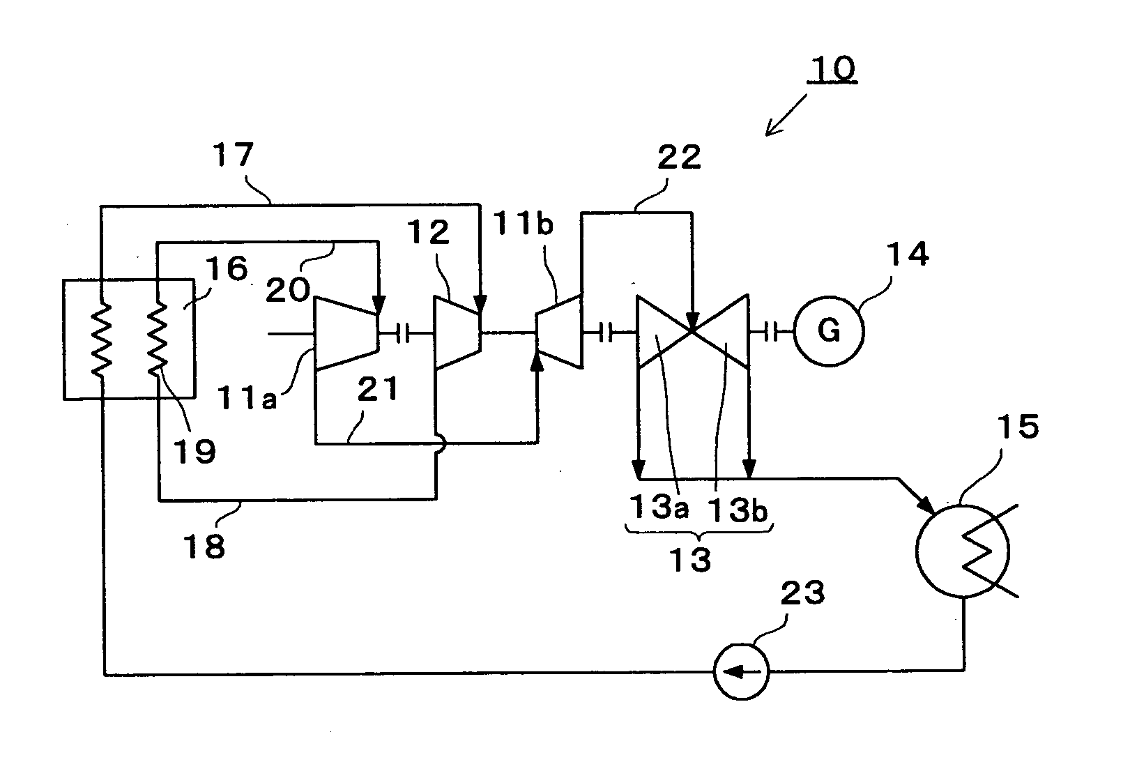
A steam turbine power plant 10 according to the first embodiment of the present invention will be described with reference to FIG. 1. FIG. 1 shows an overview of the structure of the steam turbine power plant 10.

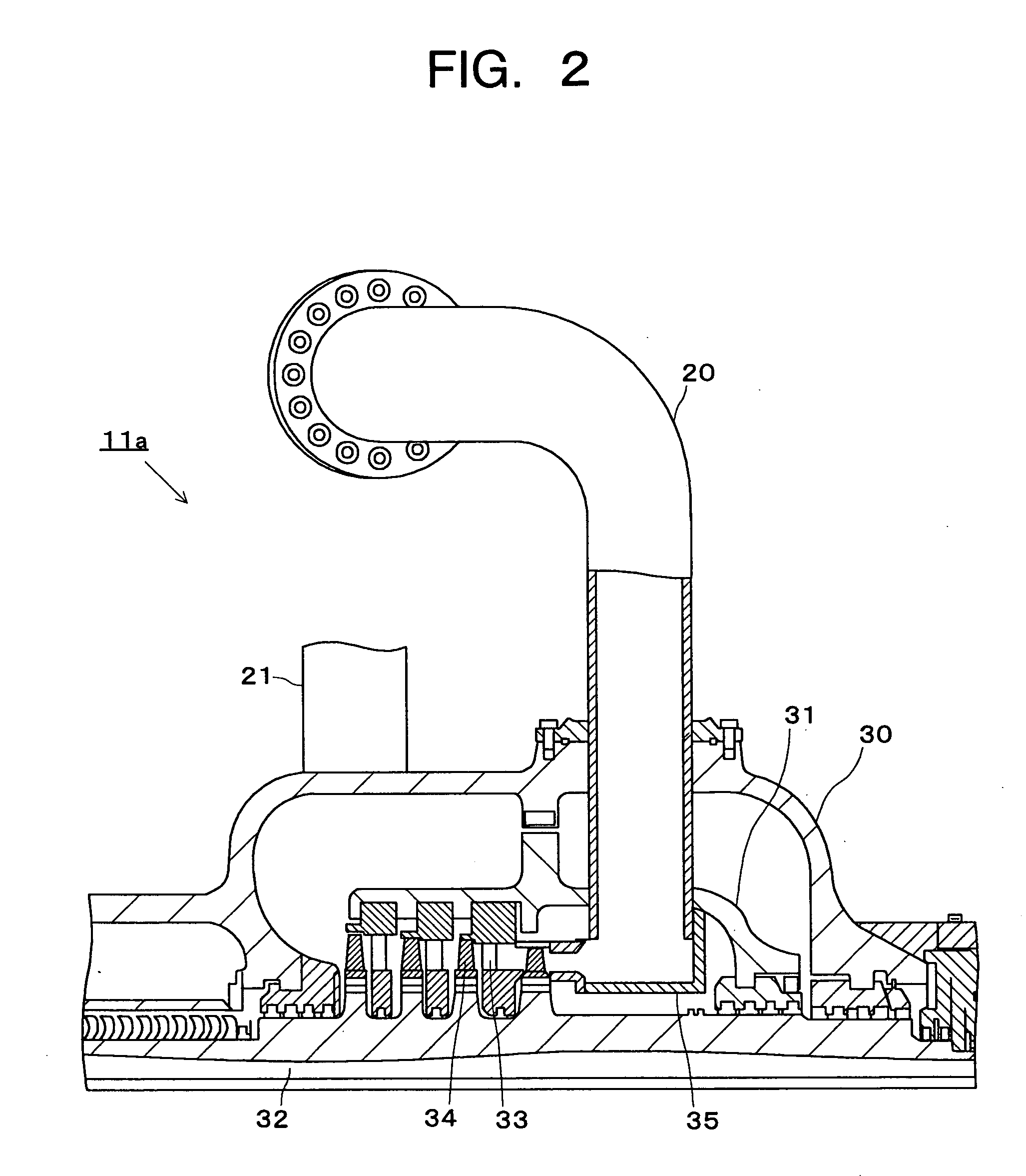
The steam turbine power plant 10 has the intermediate-pressure turbine separated into a high-temperature, high-pressure side high-temperature, intermediate-pressure turbine section 11a and a low-temperature, low-pressure side low-temperature, intermediate-pressure turbine section 11b. This steam turbine power plant 10 is mainly comprised of a high-pressure turbine 12 and the low-temperature, intermediate-pressure turbine section 11b which are disposed within the same casing, the high-temperature, intermediate-pressure turbine section 11a, a low-pressure turbine 13, a generator 14, a condenser 15, and a boiler 16. The high-temperature, intermediate-pressure turbine section 11a into which high-temperature steam having a temperature of 650° C. or more is introduced is formed...

second embodiment

A steam turbine power plant 40 according to a second embodiment of the invention will be described with reference to FIG. 3. FIG. 3 shows an overview of the structure of the steam turbine power plant 40.

The steam turbine power plant 40 is configured without having the intermediate-pressure turbine separated, and the steam turbine power plant 40 is mainly comprised of a high-pressure turbine 41, an intermediate-pressure turbine 42, a low-pressure turbine 43, a generator 44, a condenser 45 and a boiler 46. The intermediate-pressure turbine 42 into which high-temperature steam having a temperature of 650° C. or more is introduced is configured of austenitic heat-resistant steels or Ni-based alloys.

Subsequently, a work of steam in the steam turbine power plant 40 will be described.

Steam, which is heated to a temperature lower than 650° C., for example, 630° C., by and flows out of the boiler 46, flows through a main steam pipe 47 to enter the high-pressure turbine 41 at a pressur...

third embodiment

The steam turbine power plant according to a third embodiment of this invention will be described with reference to FIG. 5. The steam turbine power plant according to the third embodiment of the invention has the same structure as that of the steam turbine power plant 10 of the first embodiment except that a structure for cooling individual components is added to the high-temperature, intermediate-pressure turbine section 11a of the first embodiment.

FIG. 5 shows a sectional view of the upper half casing section of a high-temperature, intermediate-pressure turbine section 70 having a structure for mainly cooling the rotor 32 and the outer casing 30. The same reference numerals are allotted to the same elements as those of the high-temperature, intermediate-pressure turbine section 11a of the first embodiment, and their overlapped descriptions are omitted.

The high-temperature, intermediate-pressure turbine section 70 is provided with a cooling steam pipe 71 comprising a cooling st...


PUM

PropertyMeasurementUnit
temperatureaaaaaaaaaa
temperaturesaaaaaaaaaa
temperatureaaaaaaaaaa

Abstract

An intermediate-pressure turbine is divided into a high-temperature, high-pressure side high-temperature, intermediate-pressure turbine section 11a and a low-temperature, low-pressure side low-temperature, intermediate-pressure turbine section 11b, the component members of the high-temperature, intermediate-pressure turbine section 11a are formed of austenitic heat-resistant steels or Ni-based alloys, and the high-temperature, intermediate-pressure turbine section 11a is operated by steam having a temperature of 650° C. or more. Other turbines are mainly formed of ferritic heat-resistant steels. Thus, a steam turbine power plant having high thermal efficiency and being economical can be provided.

Description

CROSS-REFERENCE TO RELATED APPLICATIONS This application is based upon and claims the benefit of priority from the prior Japanese Patent Application No. 2003-283030, filed on Jul. 30, 2003 and Japanese Patent Application No. 2004-181536, filed on Jun. 18, 2004; the entire contents of which are incorporated herein by reference. BACKGROUND 1. Field of the Invention The present invention relates to a steam turbine-power plant provided with a high-temperature steam turbine, and more particularly to a steam turbine power plant provided with a steam turbine which has individual components comprised of suitable heat-resistant materials. 2. Description of the Related Art Conventionally, because the individual components configuring thermal power generation facilities are used under steam conditions including generally a steam temperature of 600° C. or less, ferritic heat-resistant steels having outstanding productivity and economical efficiency have been used for main members such as a...

Claims


Application Information

Patent Timeline
Patent Type & Authority Applications(United States)
IPC IPC(8): C21D9/00F01D5/28C22C19/05C22C19/07C22C30/00C22C38/00C22C38/58F01D25/00
CPCC22C19/055C22C19/056C22C19/058C22C30/00C22C38/001C22C38/02F01K7/16C22C38/44C22C38/46C22C38/48C22C38/50C22C38/52C22C38/54C22C38/04
Inventor TAKAHASHI, SEIKOISHII, RYUICHITSUDA, YOICHIOKITA, NOBUOYAMASHITA, KATSUYASHINOZAKI, YUKIOFUKUDA, MASAFUMITAKAHASHI, TAKEO
Owner KK TOSHIBA
Why Eureka
Try Eureka