Supercharge Your Innovation With Domain-Expert AI Agents!

Voltage regulator using a variable switching frequency

a voltage regulator and variable switching frequency technology, applied in the direction of electric variable regulation, electrical instruments, electrical equipment, etc., can solve the problems of inability to meet the specification standards of inductor, inability to perform to the inductor's saturation limit, and inability to control the voltage regulator

Active Publication Date: 2016-09-13
LENOVO ENTERPRISE SOLUTIONS SINGAPORE
View PDF3 Cites 2 Cited by
  • Summary
  • Abstract
  • Description
  • Claims
  • Application Information

AI Technical Summary

Benefits of technology

The patent text describes a method for controlling a voltage regulator that includes a first high-side field-effect transistor and a first low-side field-effect transistor. The method involves monitoring the output current and the inductance of the first output inductor in the voltage regulator. The first high-side field-effect transistor and the first low-side field-effect transistor are alternately turned on at a switching frequency. The method also involves measuring changes in the inductance and rate of change in the output current and controlling the switching frequency to prevent the current through the first high-side field-effect transistor from exceeding a maximum operating current setpoint. The patent text provides a technical solution for improving the efficiency and stability of voltage regulators.

Problems solved by technology

However, such an inductor may become rather large since the physical size of an inductor is proportional to its current saturation limits.
Furthermore, age, temperature, and manufacturing imperfections can cause the current saturation limits of the inductor to become compromised or unable to perform to the inductor's specification standards.
A primary concern is that an inductor with compromised performance can lead to current runaway on the power stages of the voltage regulator that provide current to a load such as the CPU.
As the effective output inductance decreases, the ripple current through the output inductor increases, causing undue stress on the power stage of the voltage regulator.
If left unchecked, this increased ripple current can damage the switching field-effect transistors of the voltage regulator.

Method used


Image

  • Voltage regulator using a variable switching frequency
  • Voltage regulator using a variable switching frequency
  • Voltage regulator using a variable switching frequency

Examples


Embodiment Construction

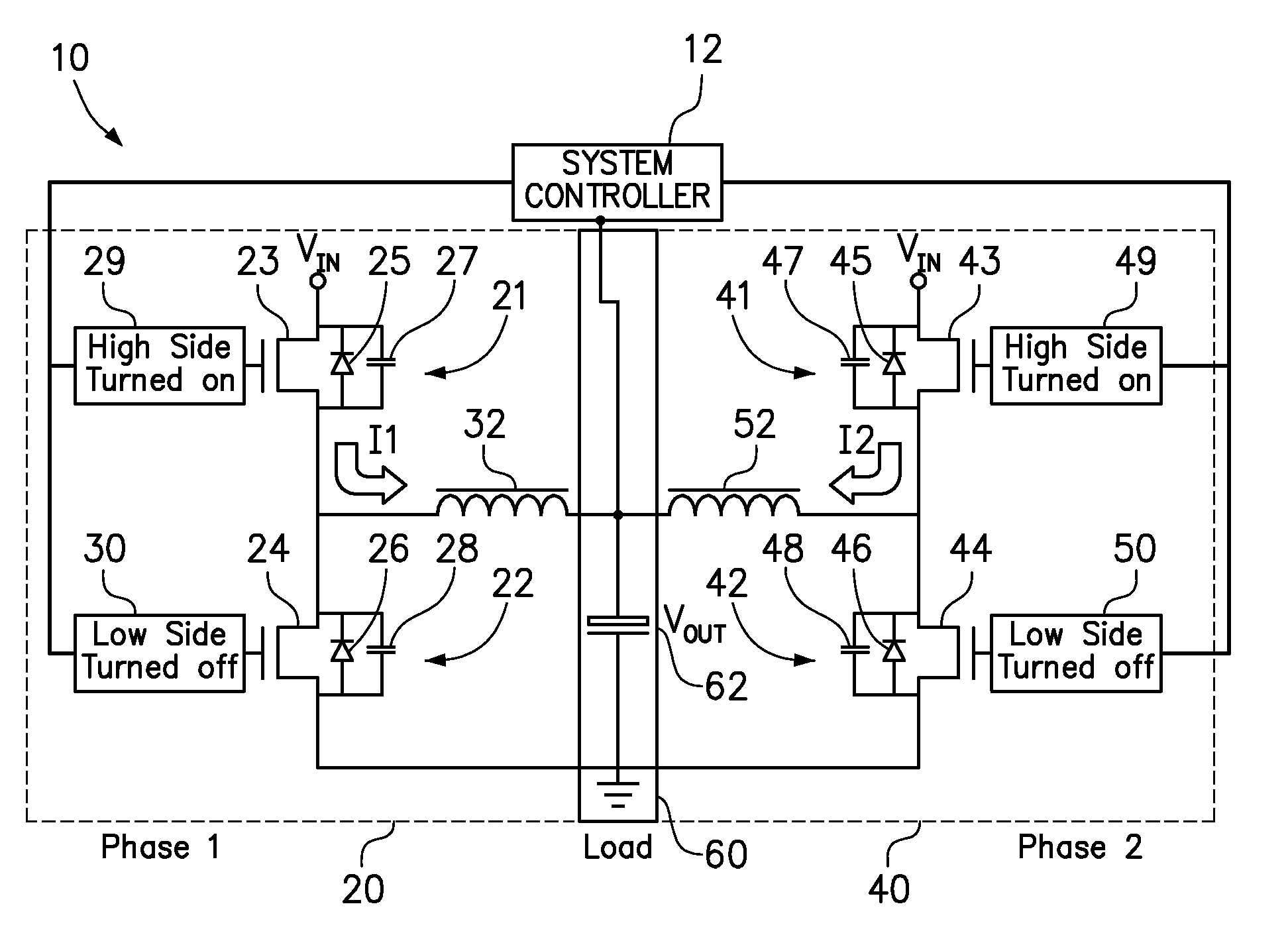
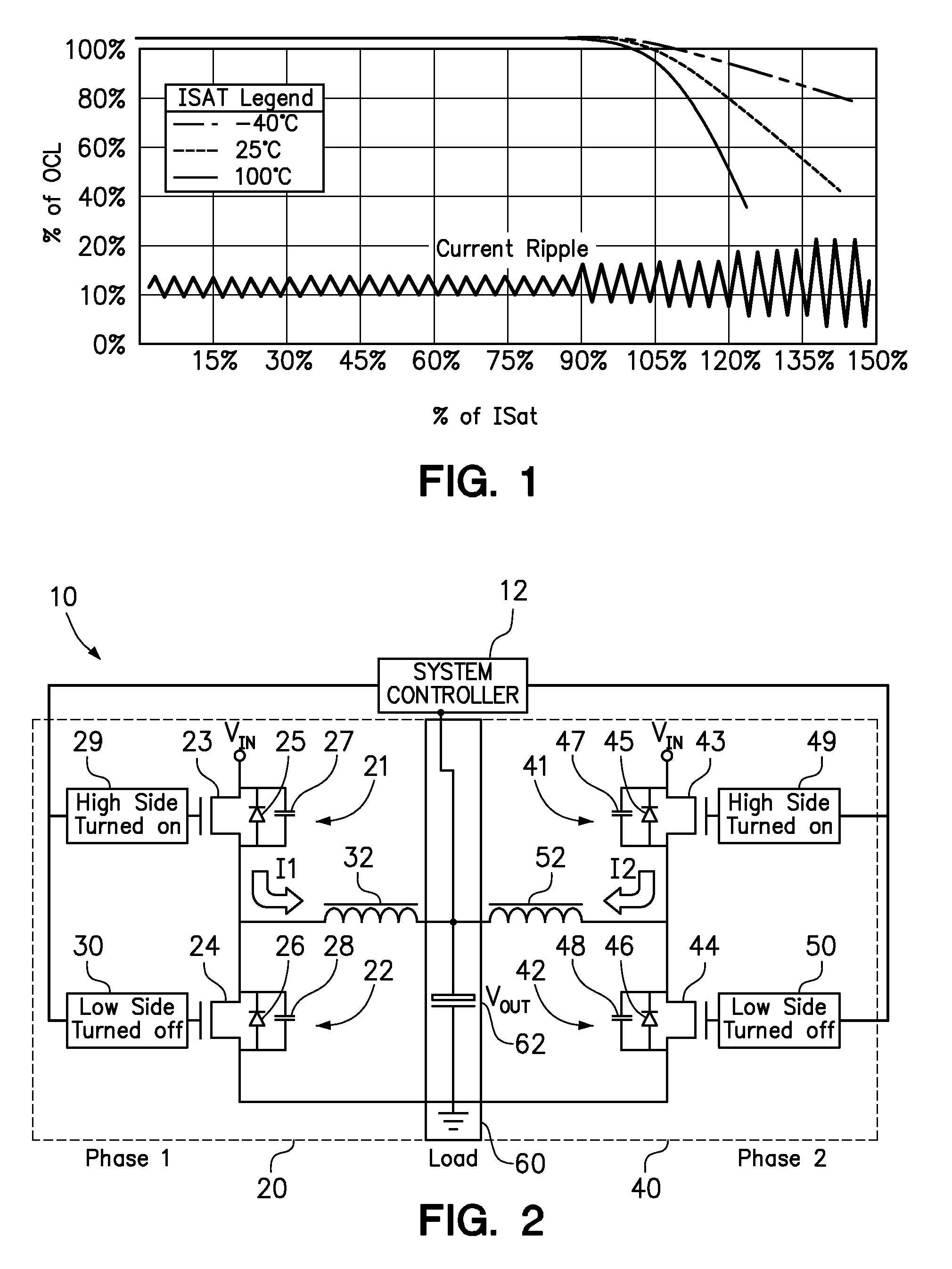
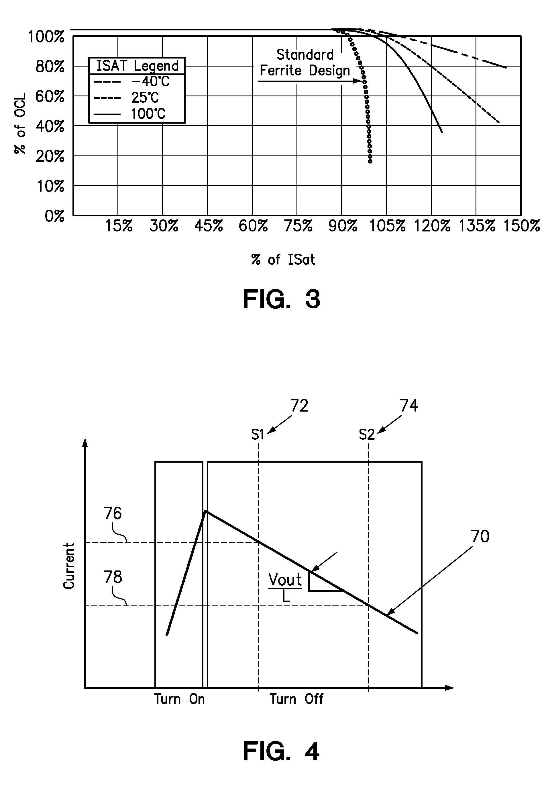
[0015]One embodiment of the present invention provides a method comprising monitoring an output current and an inductance of a first output inductor in a voltage regulator, wherein the voltage regulator includes a first high-side field-effect transistor and a first low-side field effect transistor both coupled to an input to the first output inductor. The method further comprises alternately turning on the first high-side field-effect transistor and the first low-side field-effect transistor at a switching frequency, wherein only one of the first high-side field-effect transistor and the first low-side field-effect transistor are turned on at any point in time. The method still further comprises measuring a change in the inductance of the first output inductor resulting from the first output inductor reaching current saturation and measuring a rate of change in the output current of the first output inductor. Then, the method controls the switching frequency as a function of the mea...


PUM


Abstract

A method for controlling a voltage regulator includes monitoring an output current and an inductance of an output inductor in a voltage regulator, wherein the voltage regulator includes high-side and low-side field effect transistors both coupled to an input to the first output inductor. The high-side and low-side field-effect transistors are alternately turned on at a switching frequency, wherein only one of the field-effect transistors is turned on at a time. The method measures a change in the inductance of the output inductor resulting from the output inductor reaching current saturation and measures a rate of change in the output current of the output inductor. The switching frequency is controlled as a function of the measured change in the inductance and the measured rate of change in the output current in order to prevent an amount of current through the high-side field-effect transistor from exceeding a maximum operating current setpoint.

Description

BACKGROUND[0001]1. Field of the Invention[0002]The present invention relates to the control of a voltage regulator having a plurality of switching field-effect transistors (FETs).[0003]2. Background of the Related Art[0004]Modern central processing units (CPUs) experience extreme current transients, some on the order of 100% above the maximum steady state current. Depending on the design of a voltage regulator providing power to the CPU, load changes can be in the hundreds of amps, at very high slew rates. In order to meet these high current requirements, the voltage regulator usually requires an inductor having very high current saturation limits. However, such an inductor may become rather large since the physical size of an inductor is proportional to its current saturation limits.[0005]Furthermore, age, temperature, and manufacturing imperfections can cause the current saturation limits of the inductor to become compromised or unable to perform to the inductor's specification st...

Claims


Application Information

Patent Timeline
IPC IPC(8): H02M3/158G01R19/00
CPCH02M3/158G01R19/0092H02M1/32G01R27/2611
Inventor BARNETTE, JAMAICA L.EVANS, DOUGLASTOTTEN, BRIAN C.
Owner LENOVO ENTERPRISE SOLUTIONS SINGAPORE
Features
  • R&D
  • Intellectual Property
  • Life Sciences
  • Materials
  • Tech Scout
  • Unparalleled Data Quality
  • Higher Quality Content
  • 60% Fewer Hallucinations
Learn More