Universal bifurcated stanchion for handrail systems

a technology of handrails and stanchion posts, applied in the field of handrails, can solve the problems of difficult installation, difficult installation, time-consuming and costly, etc., and achieve the effects of saving labor, facilitating installation, and yielding material, weight, labor and overall cost savings

Inactive Publication Date: 2016-09-20
SIMMONS HOWARD C
View PDF17 Cites 4 Cited by
  • Summary
  • Abstract
  • Description
  • Claims
  • Application Information

AI Technical Summary

Benefits of technology

[0005]It is a primary object of the invention to provide a versatile “universal” handrail post stanchion that will save labor and facilitate installation of virtually all railing posts and associated post-to-post structural arrangements including installations on stairs, slopes and on flat horizontal base surfaces without requiring any drilling or other modification of the stanchions at installation.
[0006]It is a further object to provide an alternative to making the upright portion of the stanchion in solid form, to yield material, weight, labor and overall cost savings, while preserving the needed strength.SUMMARY OF THE INVENTION
[0007]The forgoing objects have been accomplished in the present invention of a novel stanchion, for insertion into and support of a tubular post of a handrail system for installation on a horizontal surface, slope or staircase. The stanchion is configured with a bottom flange attached to a tubular upright portion. The upright portion is bifurcated, forming a mirror-image pair of arcuate sidewalls separated at side edges by a pair of vertical slots extending upwardly from closed low ends near the flange to open ends at the top of the upright portion. The slots are sized in width to allow passage of a handrail system bottom safety member passing through a pair of drilled holes in the post at any desired spacing above the flange, with never any need for drilling the stanchion. If required to ensure against deformation of the upright portion from external forces impacting the handrail system, reinforcement can be selectably located and deployed in a manner that avoids interference with any desired location of the bottom safety member.

Problems solved by technology

Safety, building and code regulations limit the separation between safety members, and also limit the spacing between the bottom safety member and the underlying base surface, thus raising physical interference issues since installation of the bottom safety member requires it to pass through the posts in the same low end region already necessarily occupied by the stanchions.
In practice, the stanchion height is typically made to extend above the upper limit for height of the bottom safety member allowed by code, while the height selected for ornamental design purposes can range far below the code limit, consequently installation of handrail systems using stanchions of known art routinely requires drilling not only through the hollow post walls but also through the (usually solid steel) stanchion, a burden that makes installation very tedious, time-consuming and costly.

Method used


Image

  • Universal bifurcated stanchion for handrail systems
  • Universal bifurcated stanchion for handrail systems
  • Universal bifurcated stanchion for handrail systems

Examples


Embodiment Construction

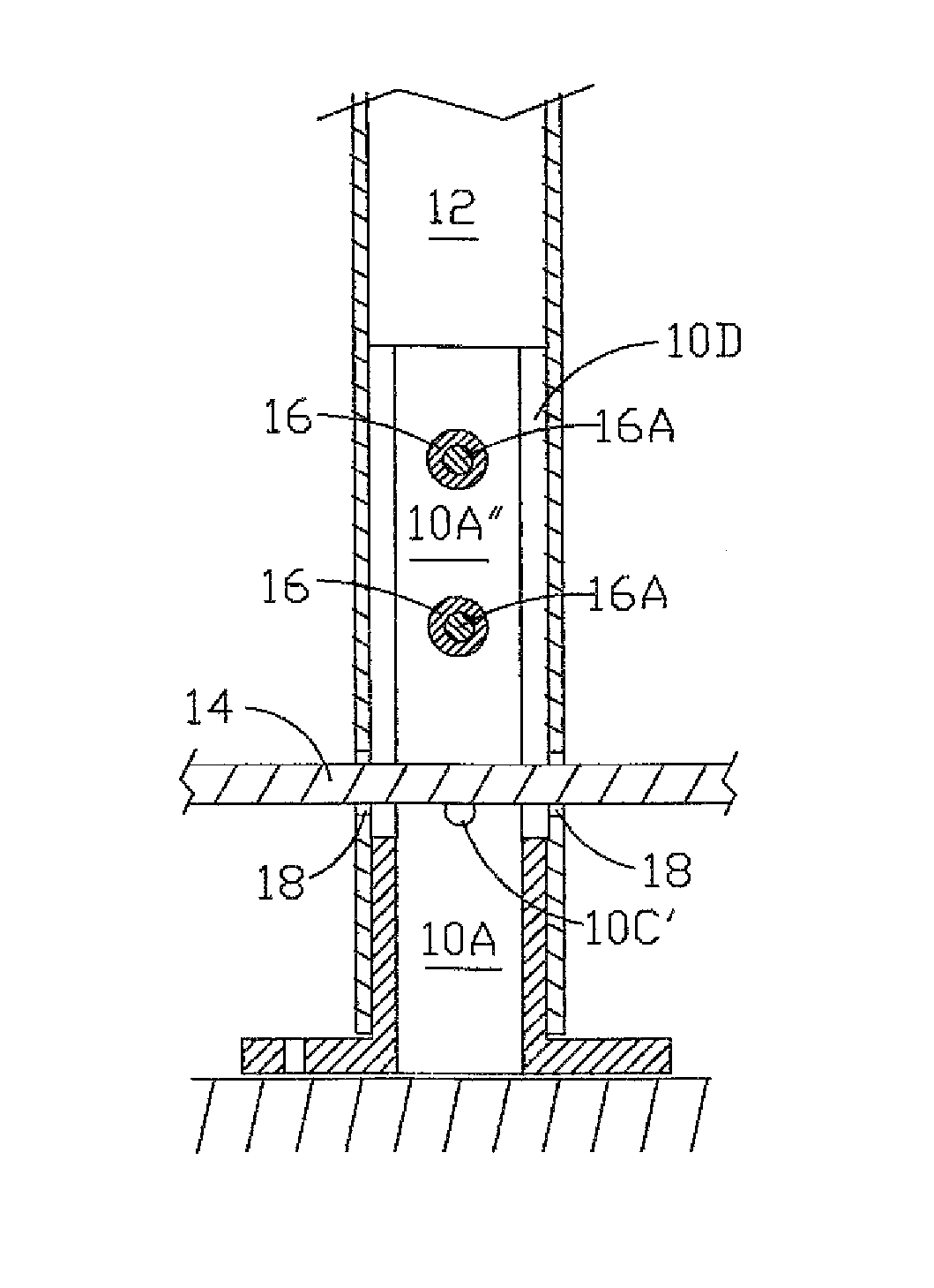
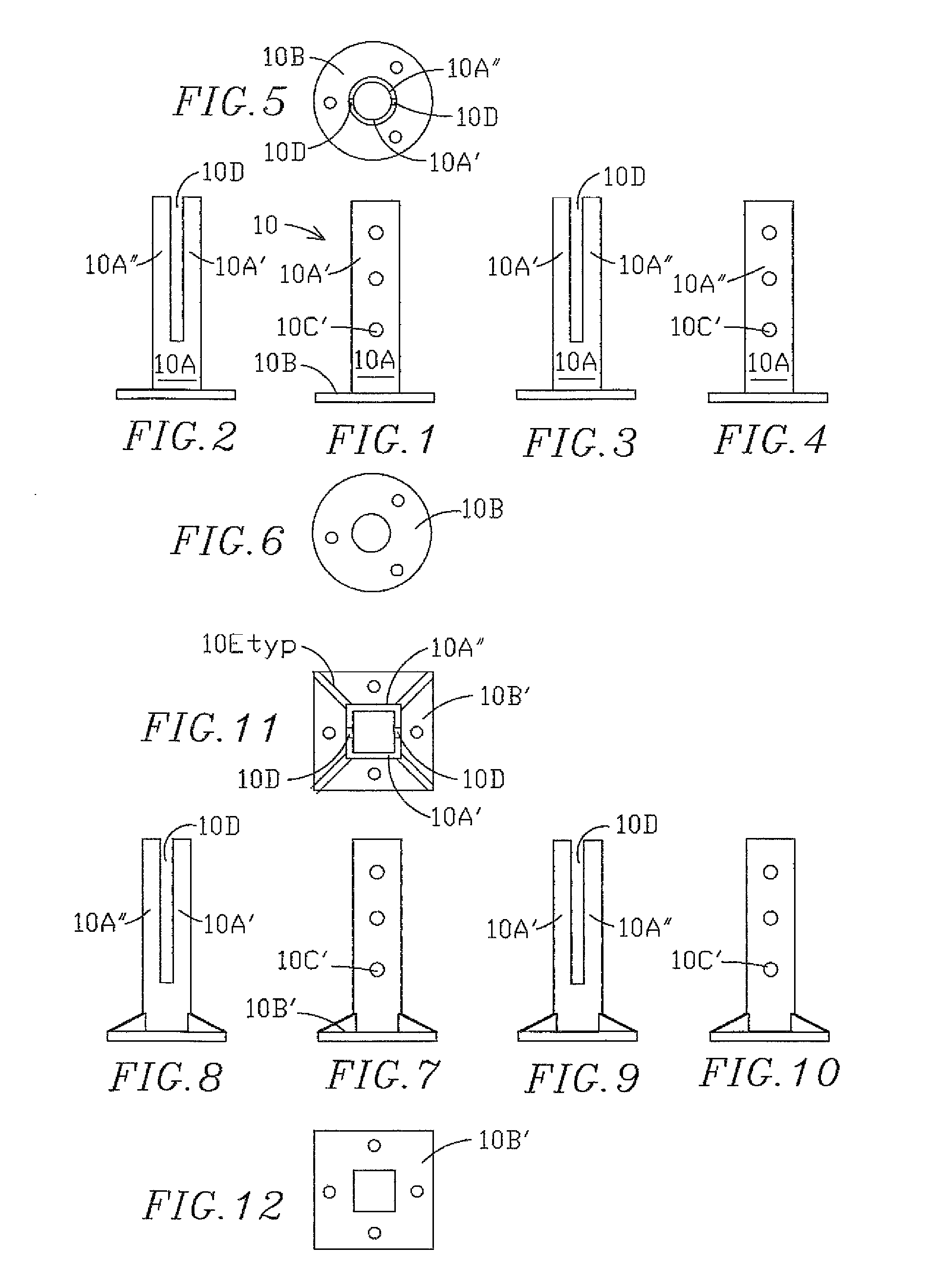
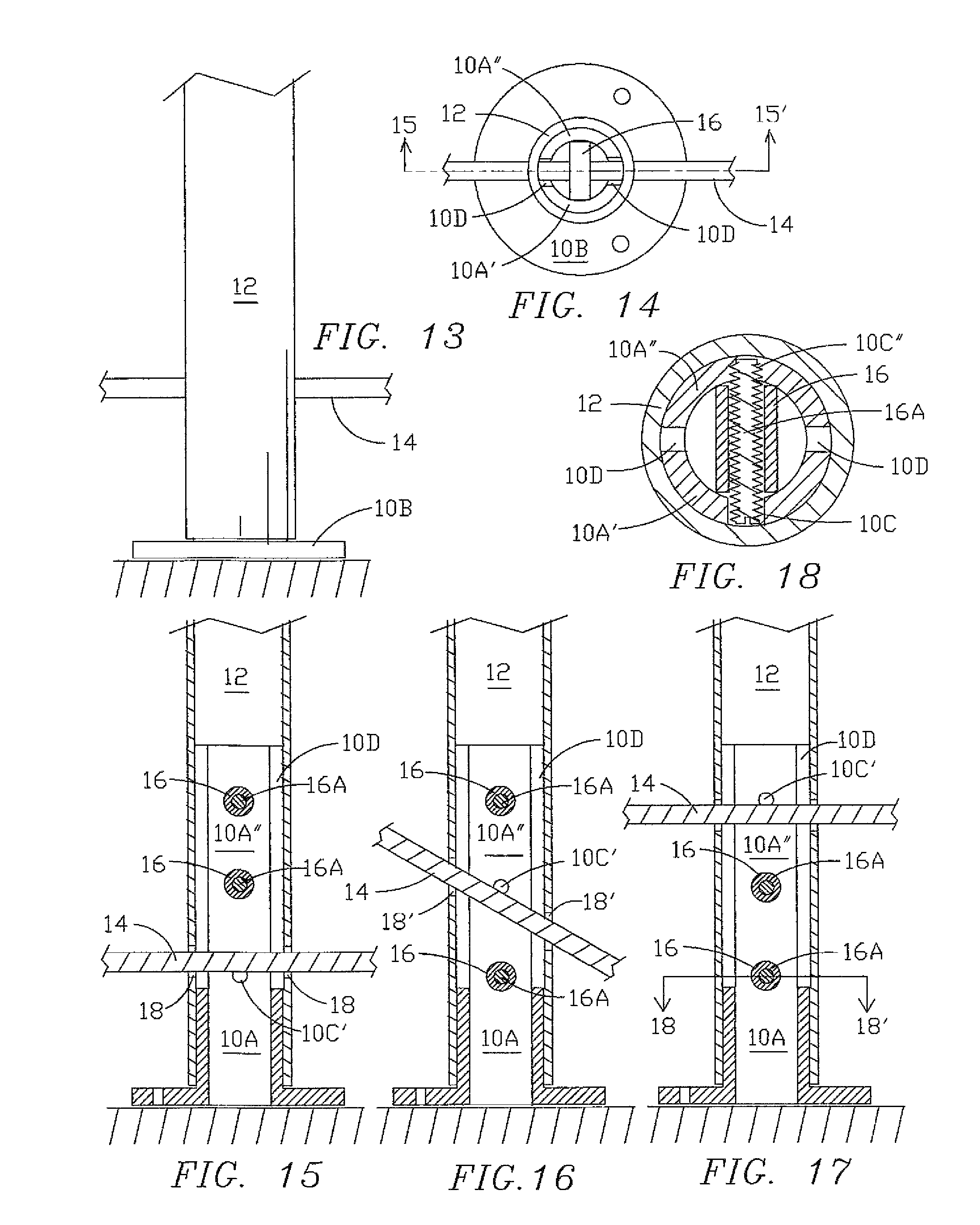
[0030]FIG. 1 is a front elevational view of a stanchion 10 of the present invention showing the basic structure of an upright portion 10A integrally attached to a bottom mounting flange portion 10B. A preferred embodiment is configured with a vertical array of three unthreaded holes 10C in the front arcuate sidewall 10A′, visible in this view. At the rear of stanchion 10, not visible in this FIG. 1 view, a second arcuate sidewall of identical outline shape is located in mirror-image relation. (see FIG. 4).

[0031]FIG. 2 is a side view of the stanchion 10 of FIG. 1 showing the upright portion 10A with its major upper portion bifurcated into two arcuate sidewalls 10A′ and 10A″, separated by a pair of vertical slots 10D extending from closed lower ends located at a designated height above the flange portion (10B, FIG. 1) to their open upper ends located at the top edge of upright portion 10A.

[0032]FIG. 3 is the opposite side view of the stanchion of FIGS. 1 and 2, showing the bifurcated ...


PUM


Abstract

A novel stanchion, for insertion into and support of a tubular post of a handrail system for installation on a horizontal surface, slope or staircase, is configured with a bottom flange attached to a tubular upright portion. The upright portion is bifurcated, forming a mirror-image pair of arcuate sidewalls separated at side edges by a pair of vertical slots extending upwardly from closed low ends near the flange to open ends at the top of the upright portion. The slots are sized in width to allow passage of a handrail system bottom safety member passing through a pair of drilled holes in the post at any desired spacing above the flange, with never any need for drilling the stanchion. If required to ensure against deformation of the upright portion from external forces impacting the handrail system, reinforcement can be selectably located and deployed in a manner that avoids interference with any desired location of the bottom safety member.

Description

FIELD OF THE INVENTION[0001]The present invention is in the field of handrails including indoor and outdoor handrail systems installed over flat horizontal surfaces, inclined surfaces and stairs, with safety members extending between posts. More particularly it relates to stanchions for supporting posts of handrail systems designed for horizontal surfaces, sloping surfaces and stairs.BACKGROUND OF THE INVENTION[0002]Handrails, whether above horizontal surfaces, slopes or stairs, are generally supported on a series of posts whose lower ends are fastened to the underlying base surface via some form of stanchion. As the structural “backbone” of a handrail system, the stanchion is required to withstand high levels of stress whenever the handrail is impacted by strong external force. For child protection and public safety, building code regulations call for some form of safety grillwork or mesh extending across the space between the posts, typically extending down to a bottom safety memb...

Claims


Application Information

Patent Timeline
Patent Type & Authority Patents(United States)
IPC IPC(8): E04H17/22E04H12/22
CPCE04H17/22E04H12/2261E04H12/2276E04F11/1812
Inventor SIMMONS, HOWARD C.
Owner SIMMONS HOWARD C
Why Eureka
Try Eureka