Clamp-on ultrasonic fluid flow meter system

a fluid flow meter and ultrasonic technology, applied in the direction of volume/mass flow measurement, measurement devices, instruments, etc., can solve the problems of reducing affecting the accuracy of the fluid flow meter, etc., to achieve the effect of preventing the propagation of structure-borne nois

Active Publication Date: 2016-09-20
KING FAHD UNIVERSITY OF PETROLEUM AND MINERALS
View PDF13 Cites 12 Cited by
  • Summary
  • Abstract
  • Description
  • Claims
  • Application Information

AI Technical Summary

Benefits of technology

This patent describes a system that uses ultrasonic waves to measure fluid flow in pipes. The system includes a way to filter out noise from the pipe structure by modifying the pipe with corrugations that meet a specific condition called Bragg resonance. This helps to accurately measure the fluid flow and prevent interference from the pipe structure. The system can also use a cladding material with periodic corrugations or alternating materials that meet Bragg's condition to attach to the pipe. Overall, this technology improves the accuracy of ultrasonic fluid flow meters and allows for better measurement of fluid flow in pipes.

Problems solved by technology

In such a metering system, a persistent problem has been how to attenuate a structural borne ultrasonic signal component that appears as noise over the fluid borne ultrasonic signal component used in measuring the fluid flow.
This is particularly a problem when the fluid is in the gaseous state, which produces a weak signal when irradiated by ultrasonic waves, so that the weak signal reflection of the incident ultrasonic wave may be lost in or modified by the structural noise propagated in the pipe.
Although many techniques have been tried, none of these techniques have been entirely successful in overcoming structural pipe noise when using a clamp-on ultrasonic fluid flow meter.

Method used


Image

  • Clamp-on ultrasonic fluid flow meter system
  • Clamp-on ultrasonic fluid flow meter system
  • Clamp-on ultrasonic fluid flow meter system

Examples


Embodiment Construction

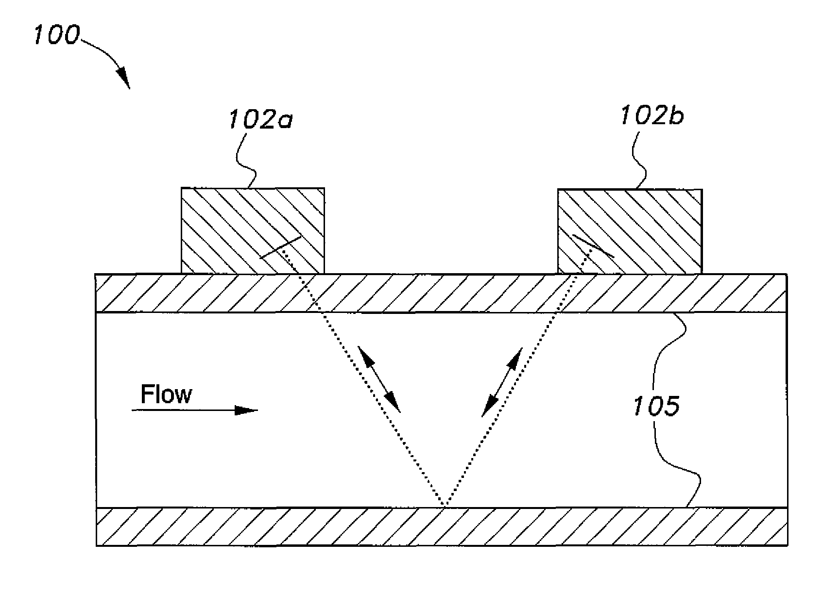
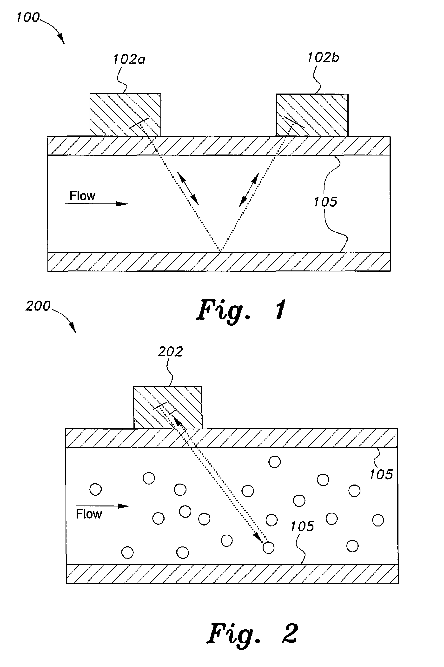
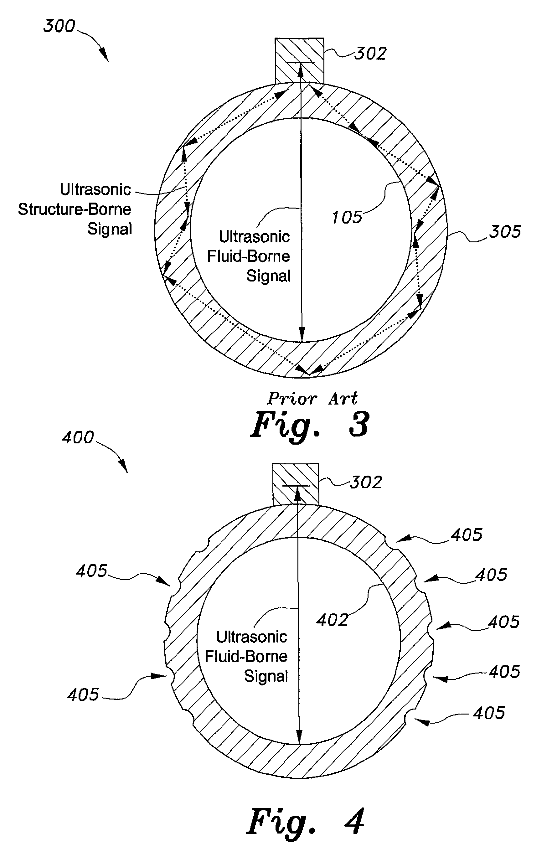
[0018]The clamp-on ultrasonic fluid flow meter system is an apparatus that includes structures that rely on Bragg resonance to filter out a pipe structure-borne ultrasonic wave component. The system uses a modified fluid flow pipe having corrugations defined in or attached to the pipe wall, the corrugations coupling incident and reflected ultrasound structure-borne wave components in such a manner that the incident and reflected waves undergo maximum destructive interference at Bragg resonance, thereby preventing the propagation of noise that would otherwise interfere with ultrasound fluid flow meter measurements. Thus, the periodically corrugated pipe wall acts as a stopband filter.

[0019]The clamp-on fluid flow meter may be any type of conventional clamp-on ultrasound fluid flow meter. For example, the meter may be an ultrasound meter that operates on the “time of flight” principle, which is suitable for clean liquids. Flow velocity is calculated from the difference in time (normal...


PUM


Abstract

The clamp-on ultrasonic fluid flow meter system is an apparatus that includes structures that filter out a pipe structure-borne ultrasonic wave component. The clamp-on ultrasonic fluid flow meter system provides pipes that are modified to rely on Bragg resonance to attenuate the pipe structure-borne ultrasonic wave component. In a first embodiment, the fluid flow pipe is modified with corrugations so that the periodicity of the corrugations defines a pipe wall corrugation wavelength that is one-half the wavelength of the structure-borne ultrasonic wave component, satisfying Bragg's condition and preventing propagation of structure-borne noise that might interfere with the ultrasonic fluid flow meter. In a second embodiment, a pipe clad material having periodic corrugations as described above is adhesively or magnetically attached to the fluid flow pipe. In a third embodiment, alternating materials at a periodic rate satisfying Bragg's condition are attached to the exterior of the fluid flow pipe.

Description

BACKGROUND OF THE INVENTION[0001]1. Field of the Invention[0002]The present invention relates to fluid flow measuring devices, and particularly to a clamp-on ultrasonic fluid flow meter system with improved accuracy.[0003]2. Description of the Related Art[0004]There is a considerable increase in the trend of using Clamp-On Metering products within building services and process industries. A clamp-on metering system consists of an ultrasonic transmitter and an ultrasonic receiver, which are mounted on the outer wall of the pipe carrying a flow of fluid. The measuring concept is based on transmitting an ultrasonic signal across the moving fluid, then receiving it, modified, after it encounters the fluid flowing in the pipe, and then processing the received signal to derive parameters of interest to calculate fluid flow velocity or volumetric flow rate. In such a metering system, a persistent problem has been how to attenuate a structural borne ultrasonic signal component that appears ...

Claims


Application Information

Patent Timeline
IPC IPC(8): G01F1/66
CPCG01F1/663G01F1/662G01F1/667
Inventor HAWWA, MUHAMMAD A.BAROUDI, UTHMAN
Owner KING FAHD UNIVERSITY OF PETROLEUM AND MINERALS
Why Eureka
Try Eureka