Supercharge Your Innovation With Domain-Expert AI Agents!

Digital power gating with programmable control parameter

a digital power gating and control parameter technology, applied in the field of power gating, can solve the problems of increased sub-threshold leakage current, idle cmos circuit or a portion thereof, and inability to provide useful work

Active Publication Date: 2016-09-20
VIA TECH INC
View PDF29 Cites 5 Cited by
  • Summary
  • Abstract
  • Description
  • Claims
  • Application Information

AI Technical Summary

Benefits of technology

The patent describes an integrated circuit with a global supply bus and a gated supply bus. The circuit includes a power gating system that controls the voltage of the gated supply bus. The power gating control system includes gating devices and a control system that selects between multiple gain values to adjust the voltage of the gated supply bus. The system also includes a clock controller that adjusts the clock signal to control the rate of adjusting the digital control value, and a time decoder that selects between multiple shifted versions of the digital control value to adjust the time control value. The programmable device may be a fuse array or a memory programmed with the control parameter. The technical effect of the patent is to provide a flexible and programmable power gating system for integrated circuits that can adjust the voltage of the gated supply bus to optimize power consumption and performance.

Problems solved by technology

Manufacturers have also switched to gate materials causing lower threshold voltages which has further led to increased sub-threshold leakage current.
For certain periods of time and / or under certain circumstances a CMOS circuit or a portion thereof may become idle in which it does not provide useful work.
Maintaining full power to the idle circuit is wasteful and inefficient since sub-threshold leakage current continues to flow consuming valuable energy.
This technique has not been as effective for current CMOS technologies at 40 nanometer (nm) and 28 nm and the like.

Method used


Image

  • Digital power gating with programmable control parameter
  • Digital power gating with programmable control parameter
  • Digital power gating with programmable control parameter

Examples


Embodiment Construction

[0036]The following description is presented to enable one of ordinary skill in the art to make and use the present invention as provided within the context of a particular application and its requirements. Various modifications to the preferred embodiment will, however, be apparent to one skilled in the art, and the general principles defined herein may be applied to other embodiments. Therefore, the present invention is not intended to be limited to the particular embodiments shown and described herein, but is to be accorded the widest scope consistent with the principles and novel features herein disclosed.

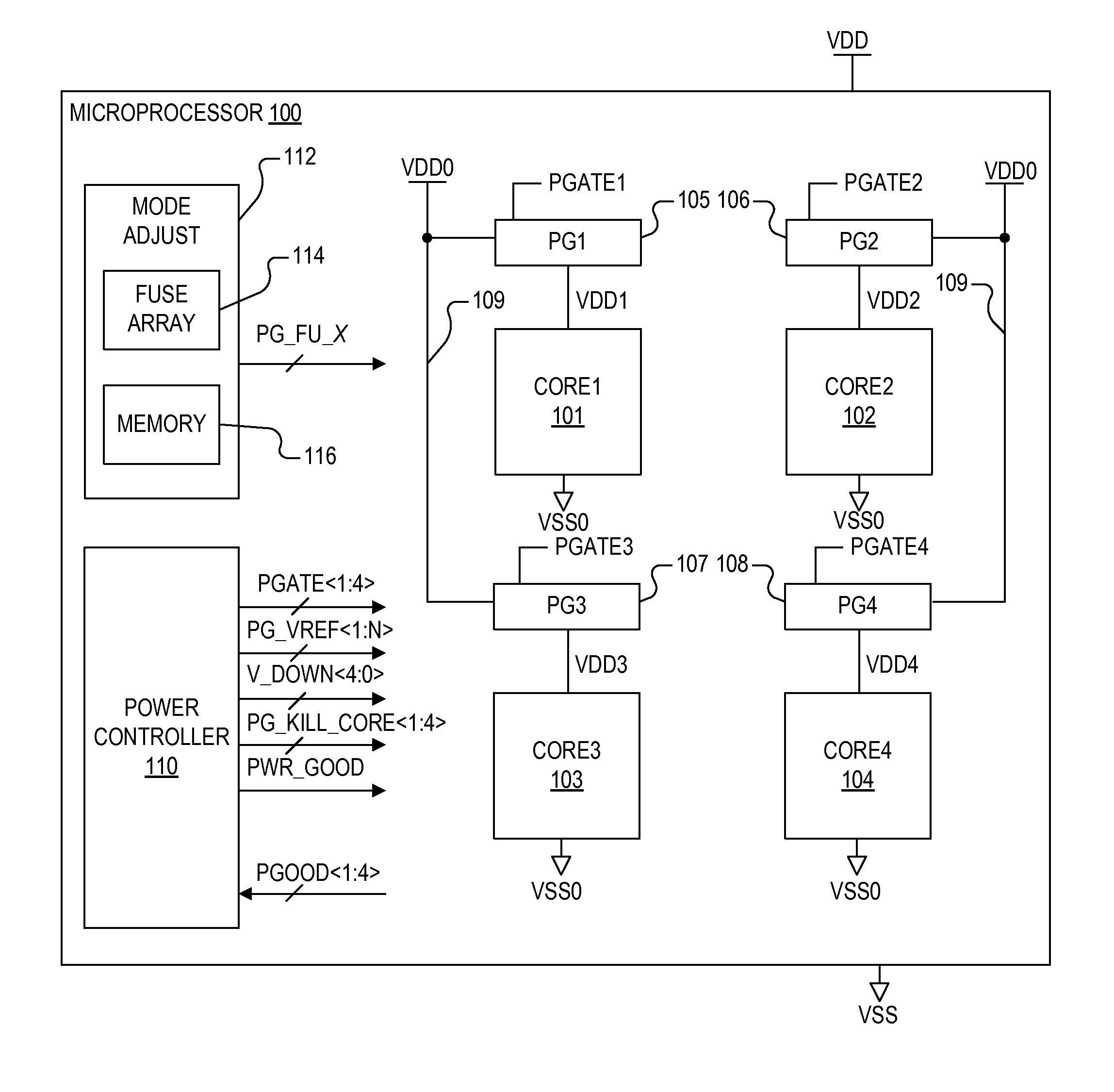
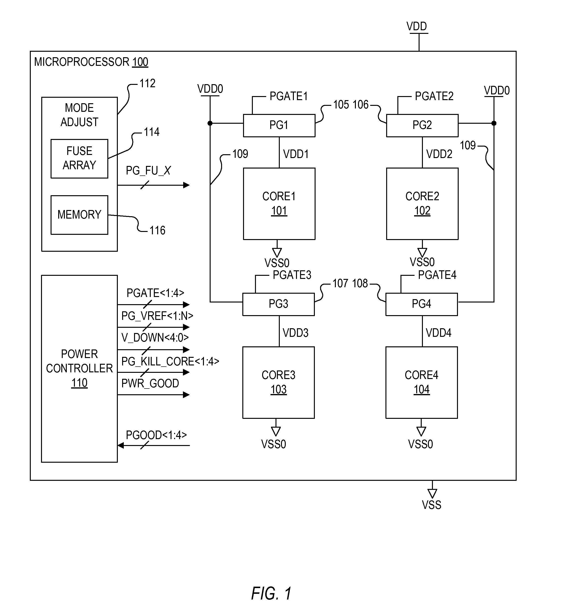
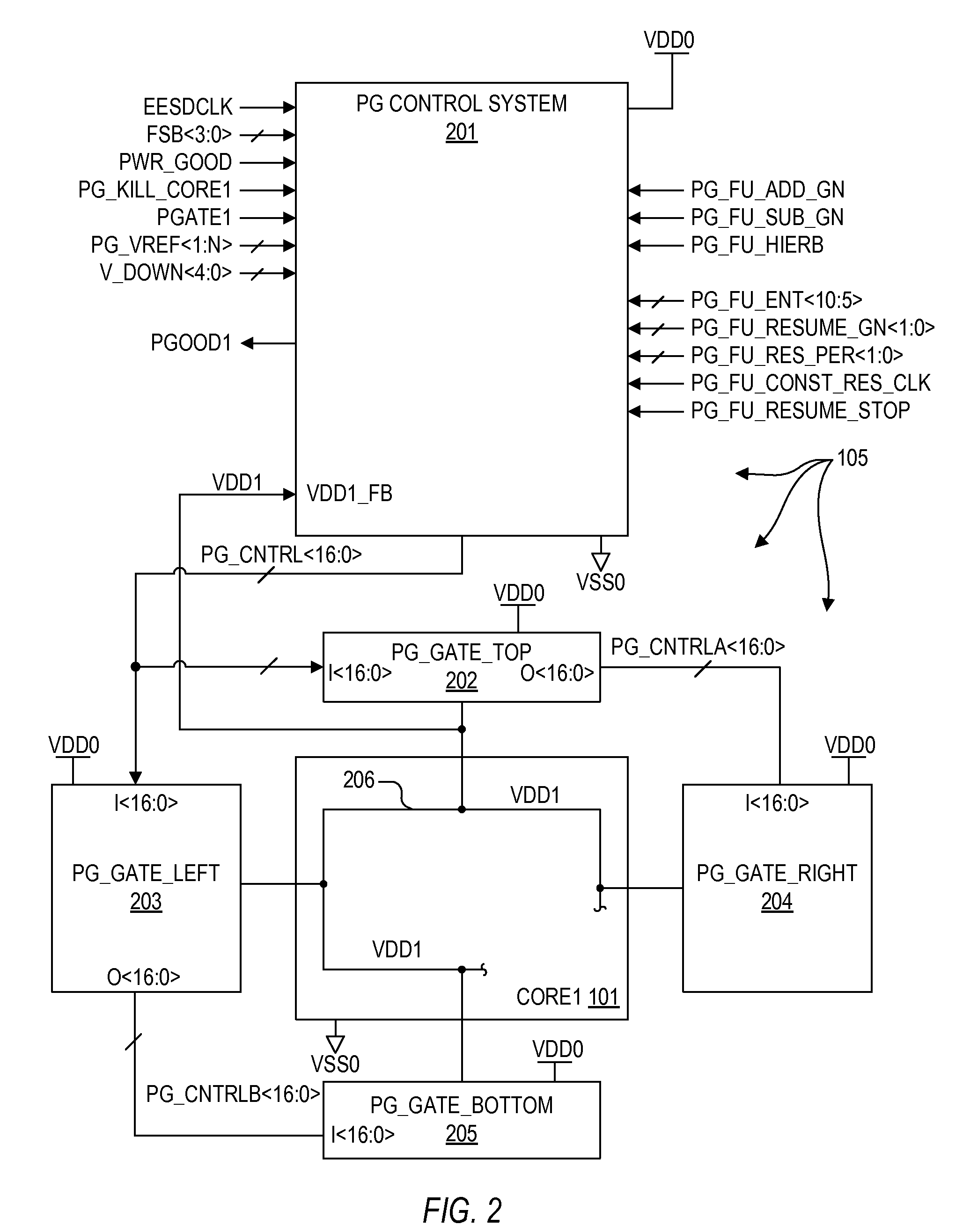
[0037]Conventional power gating has been rather crude or otherwise based on analog techniques. Conventional power gating also typically forced full power gating in which the source voltage is effectively removed, so that any stored data or logical state of the circuit, such as retained in data storage devices including memory or registers or the like, is lost. In many circumsta...


PUM


Abstract

An integrated circuit including a global supply bus, a gated supply bus, a functional circuit coupled to the gated supply bus, a programmable device that stores a programmed control parameter, and a digital power gating system. The digital power gating system includes gating devices and a power gating control system. Each gating device is coupled between the global and gated supply buses and each has a control terminal. The power gating control system controls a digital control value to control activation of the gating devices. The power gating control system is configured to perform a power gating operation by adjusting the digital control value to control a voltage of the gated supply bus relative to the voltage of the global supply bus. The power gating operation may be adjusted using the programmed control parameter. The programmable device may be a fuse array or a memory programmed with programmed control parameter.

Description

CROSS REFERENCE TO RELATED APPLICATION(S)[0001]This application claims priority to the following U.S. Provisional Patent Application which is hereby incorporated by reference in its entirety for all intents and purposes.[0002]SERIALFILINGNUMBERDATETITLE61 / 831,544Jun. 05, 2013DIGITAL POWER GATING WITHDATA RETENTION61 / 930,356Jan. 22, 2014DIGITAL POWER GATING WITHSTATE RETENTION[0003]This application is related to the following co-pending U.S. Patent Applications, each of which has a common assignee and common inventors.[0004]SERIALFILINGNUMBERDATETITLEDIGITAL POWER GATING(CNTR.2638)    WITH STATE RETENTIONDIGITAL POWER GATING(CNTR.2719)    WITH GLOBAL VOLTAGESHIFTDIGITAL POWER GATING(CNTR.2720)    WITH CONTROLLEDRESUMEBACKGROUND OF THE INVENTION[0005]1. Field of the Invention[0006]The present invention relates in general to power gating, and more particularly, to a power gating system and method with at least one programmable control parameter to program operation for power gating and...

Claims


Application Information

Patent Timeline
Patent Type & Authority Patents(United States)
IPC IPC(8): G05F1/10H03K19/00
CPCH03K19/0008
Inventor LUNDBERG, JAMES R.
Owner VIA TECH INC
Features
  • R&D
  • Intellectual Property
  • Life Sciences
  • Materials
  • Tech Scout
  • Unparalleled Data Quality
  • Higher Quality Content
  • 60% Fewer Hallucinations
Learn More