
Component having a micromechanical microphone pattern

a micro-mechanical and microphone technology, applied in the direction of transducer types, loudspeakers, semi-conductor electrostatic transducers, etc., can solve the problems of high suction pressure, strong air blasts, damage to the microphone pattern, etc., and achieve the effect of increasing the robustness of the microphone pattern to highly dynamic pressure fluctuations and increasing the resistance to compression

Active Publication Date: 2016-09-20
ROBERT BOSCH GMBH
View PDF11 Cites 2 Cited by
  • Summary
  • Abstract
  • Description
  • Claims
  • Application Information

AI Technical Summary

Benefits of technology

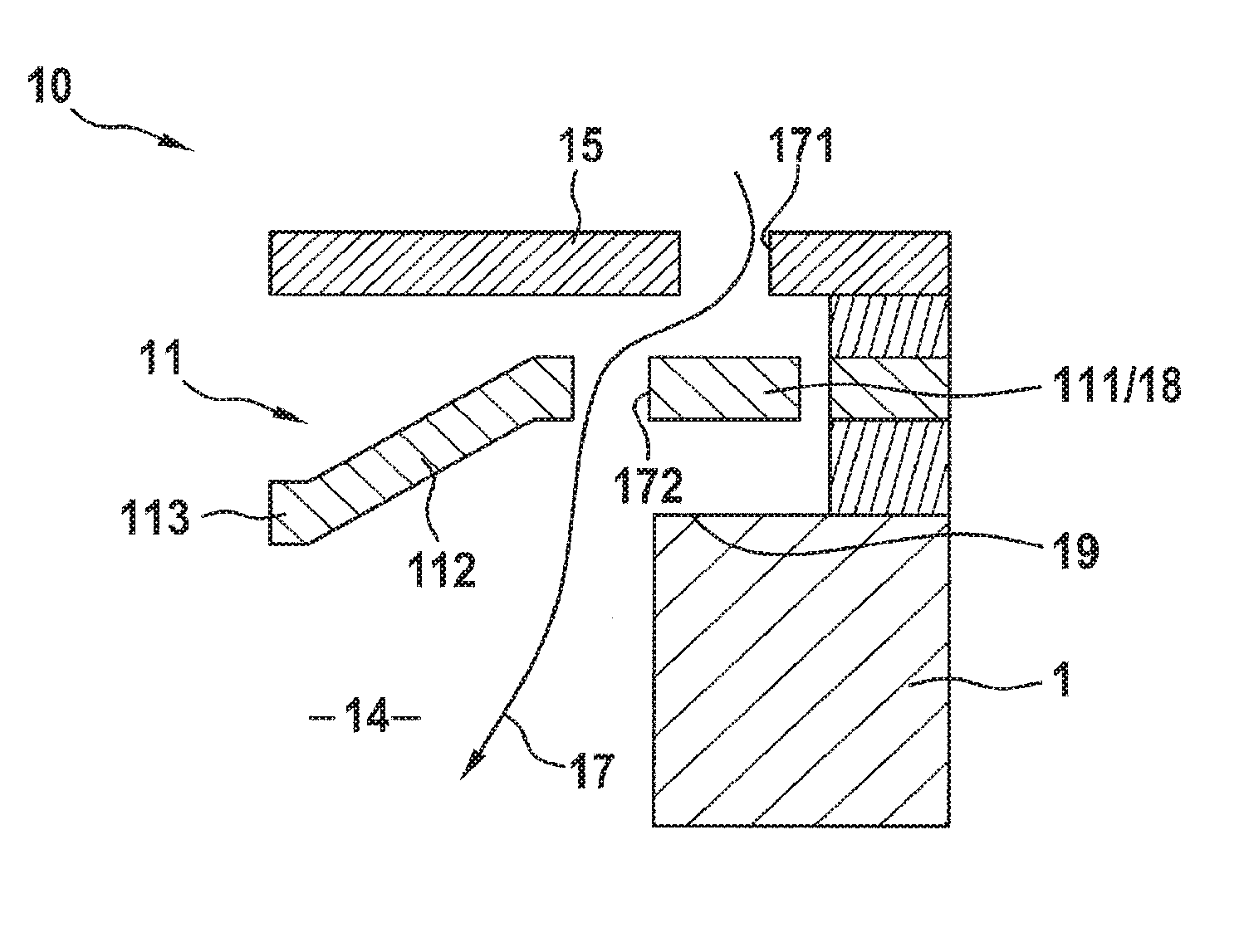
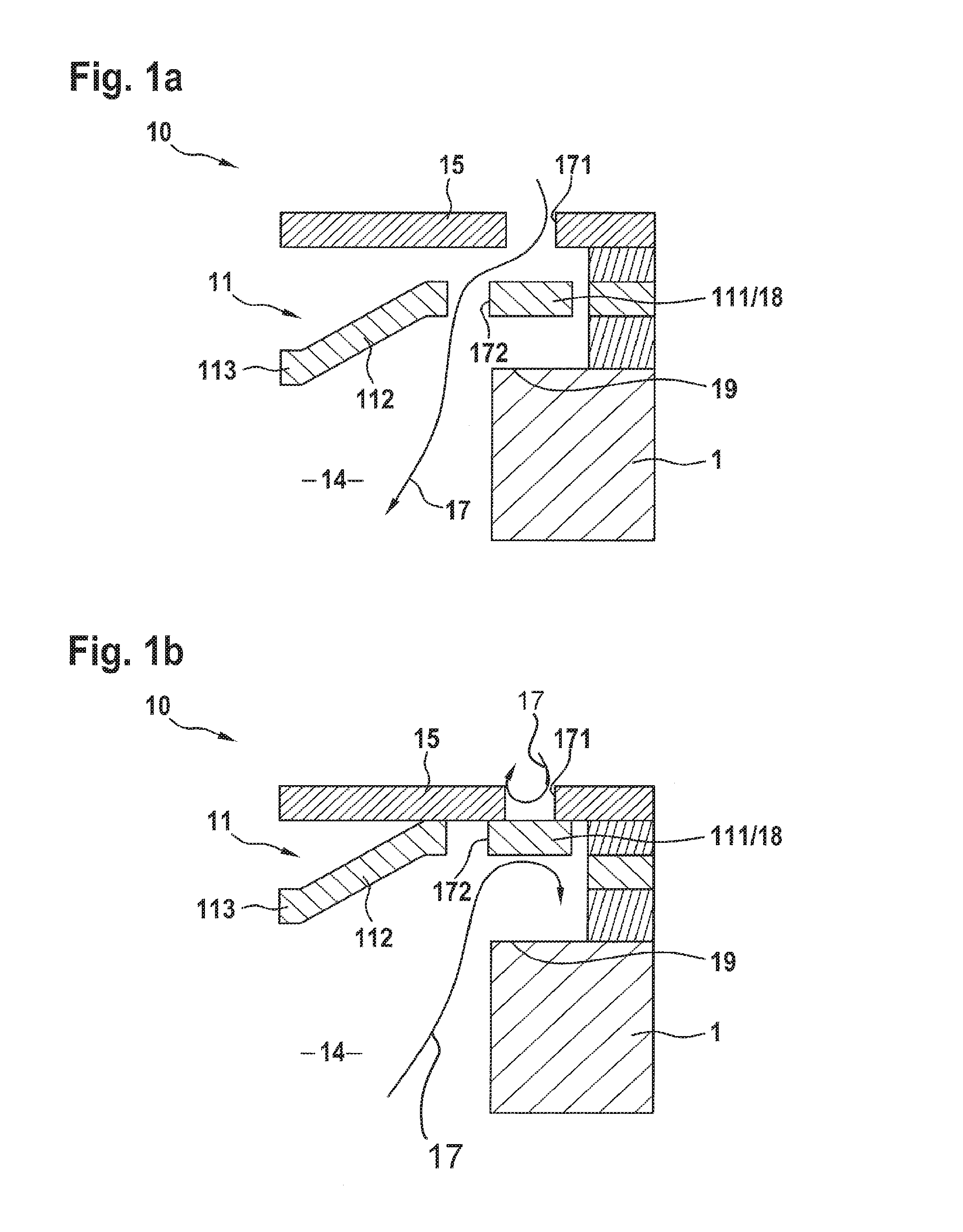
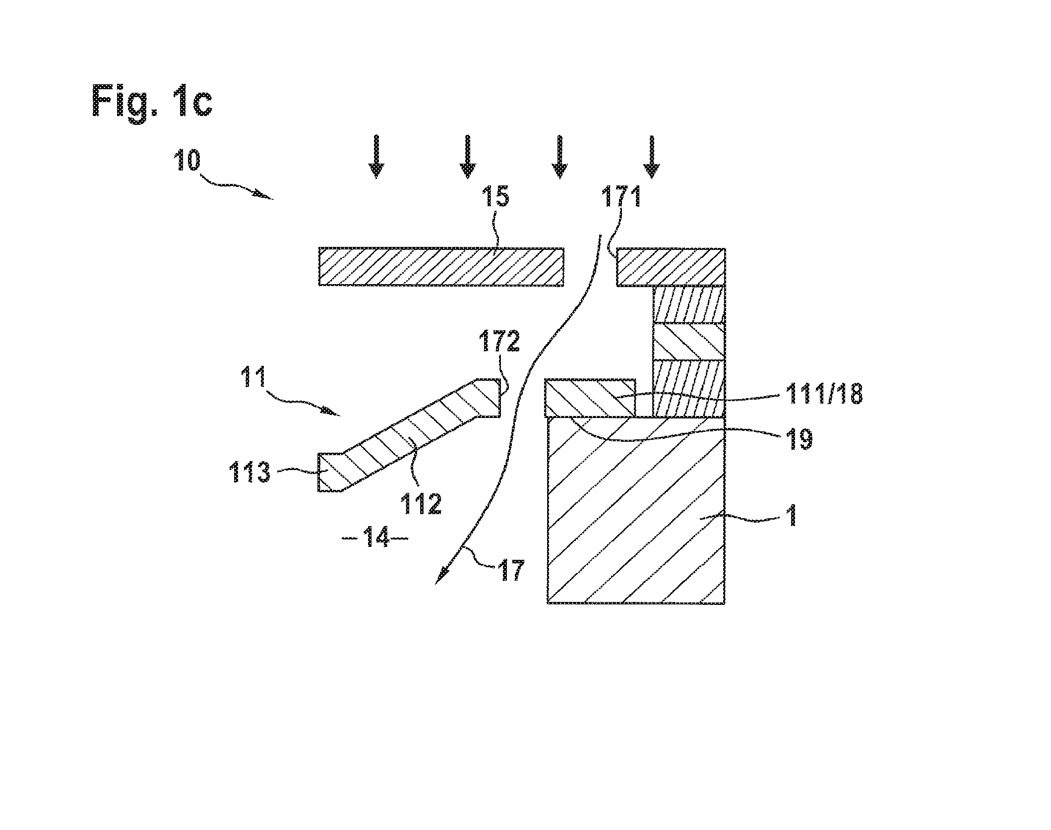
The present invention is about improving the resistance to compression of a microphone pattern, making it more robust against highly dynamic pressure fluctuations without affecting its sensitivity. One way to compensate for impact pressure overload situations is to implement an outflow channel in the diaphragm range of the microphone pattern. The outflow channel can be developed at the edge of the diaphragm area, using two pressure equalization openings that communicate with each other. This allows the diaphragm to act as a controllable closing element and quickly equalize pressure between the two sides when an impact pressure occurs. The invention also includes a stop to limit the diaphragm deflection during the opening of the outflow channel and protect against damage from an overload.

Problems solved by technology

Such overload situations, which may even lead to damage in the microphone pattern, may not, however, be totally excluded either during the production process nor at the point of use of the component.
Thus, during the production process, in “pick'n place” assembly, very high suction pressures are used, and also at the place of use of the component, strong air blasts may occur, such as are caused by an air pistol, for example.

Method used


Image

  • Component having a micromechanical microphone pattern
  • Component having a micromechanical microphone pattern
  • Component having a micromechanical microphone pattern

Examples


Embodiment Construction

[0019]The microphone patterns of components 10, 20 and 30 are each implemented in a layer construction on a semiconductor substrate 1. They include an acoustically active diaphragm 11 which spans a sound hole 14 on the backside of the substrate. Moreover, the microphone patterns include a stationary acoustically penetrable counterelement 15 which, in the case of components 10 and 20, is situated in the layer construction above diaphragm 11, and in the case of component 30, in the layer construction below diaphragm 11. In particular, the sectional representations of FIGS. 1a and 3a, the microphone patterns of components 10 and 30 in the passive operating mode show, illustrate that diaphragm 11 is in each case made up of an edge region 111, a parallel-sided middle region 113 and a transitional region 112 between edge region 111 and middle region 113, and that, between edge region 111 of diaphragm 11 and counterelement 15 there is a shorter distance than between parallel-sided middle r...


PUM


Abstract

Measures are provided for increasing the resistance to compression of a component having a micromechanical microphone pattern. In particular, the robustness of the microphone pattern to highly dynamic pressure fluctuations is to be increased, without the microphone sensitivity, i.e. the microphone performance, being impaired. The microphone pattern of such a component is implemented in a layer construction on a semiconductor substrate and includes at least one acoustically active diaphragm, which spans a sound hole on the substrate backside, and a stationary acoustically penetrable counterelement having through hole openings, which is situated above / below the diaphragm in the layer construction. At least one outflow channel is developed which makes possible a rapid pressure equalization between the two sides of the diaphragm. In addition, at least one controllable closing element is provided, with which the at least one outflow channel is optionally able to be opened or closed.

Description

FIELD OF THE INVENTION[0001]The present invention relates to a component having at micromechanical microphone pattern, which is implemented in a layer construction on a semiconductor substrate. The microphone pattern includes an acoustically active diaphragm, which spans a sound hole on the backside of the substrate, and a stationary acoustically penetrable counterelement, having through hole openings, which is situated in the layer construction above or below the diaphragm.BACKGROUND INFORMATION[0002]The diaphragm's being acted upon by sound takes place via the sound hole in the substrate and / or via the through holes in the counterelement. The diaphragm deflections resulting from this, perpendicular to the layer planes, are able to be detected capacitively, for example. For this, the microphone pattern is equipped with a capacitor device which includes at least one deflectable electrode on the diaphragm and at least one stationary electrode on the counterelement. The volume directl...

Claims


Application Information

Patent Timeline
Patent Type & Authority Patents(United States)
IPC IPC(8): H01L29/84H04R19/04H04R19/00
CPCH04R19/04H01L29/84H04R19/005B81B7/0041B81B2201/0257H04R2201/003
Inventor SCHELLING, CHRISTOPHSINGER, STEFANZOELLIN, JOCHEN
Owner ROBERT BOSCH GMBH
Learn More