
Base station, communication system, and communication method

Inactive Publication Date: 2016-09-20
FUJITSU LTD
View PDF24 Cites 0 Cited by
  • Summary
  • Abstract
  • Description
  • Claims
  • Application Information

AI Technical Summary

Benefits of technology

The invention provides a base station with a transmitter and a receiver, and a processor to detect a mobile station communicating with a different device. The base station can decrease the power of the first radio signal to avoid interfering with the communication between the second mobile station and the communication device. The technical effect of this invention is to improve the efficiency and reliability of wireless communication.

Problems solved by technology

In the case where a macro UE (MUE (Macro User Equipment)) that is not permitted to connect to a femto base station is present within the femtocell, the SINR (signal to interference and noise ratio) of the macro UE may be deteriorated due to the interference from the femto base station.
Meanwhile, if the transmission power of the femto base station is decreased when a victim UE is not present, the communication throughput within the femtocell may decrease unnecessarily.

Method used


Image

  • Base station, communication system, and communication method
  • Base station, communication system, and communication method
  • Base station, communication system, and communication method

Examples


first embodiment

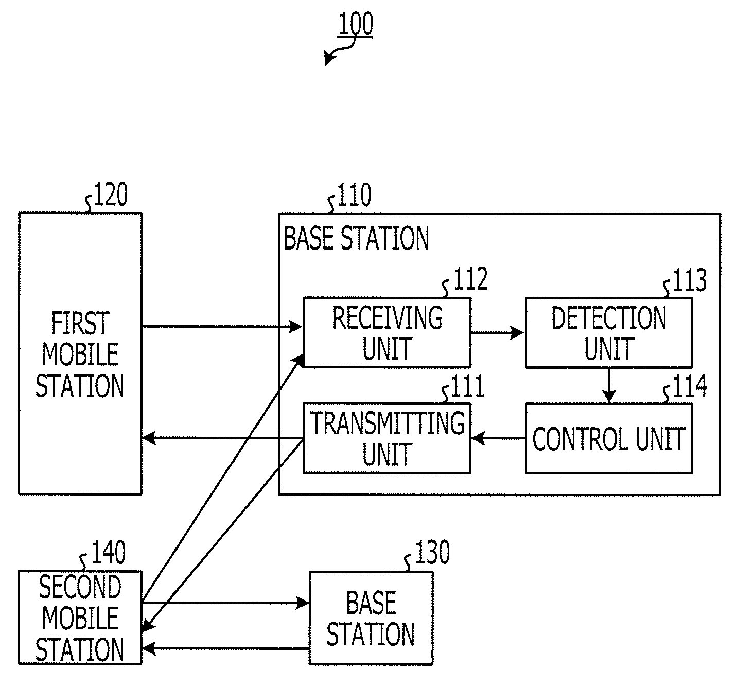
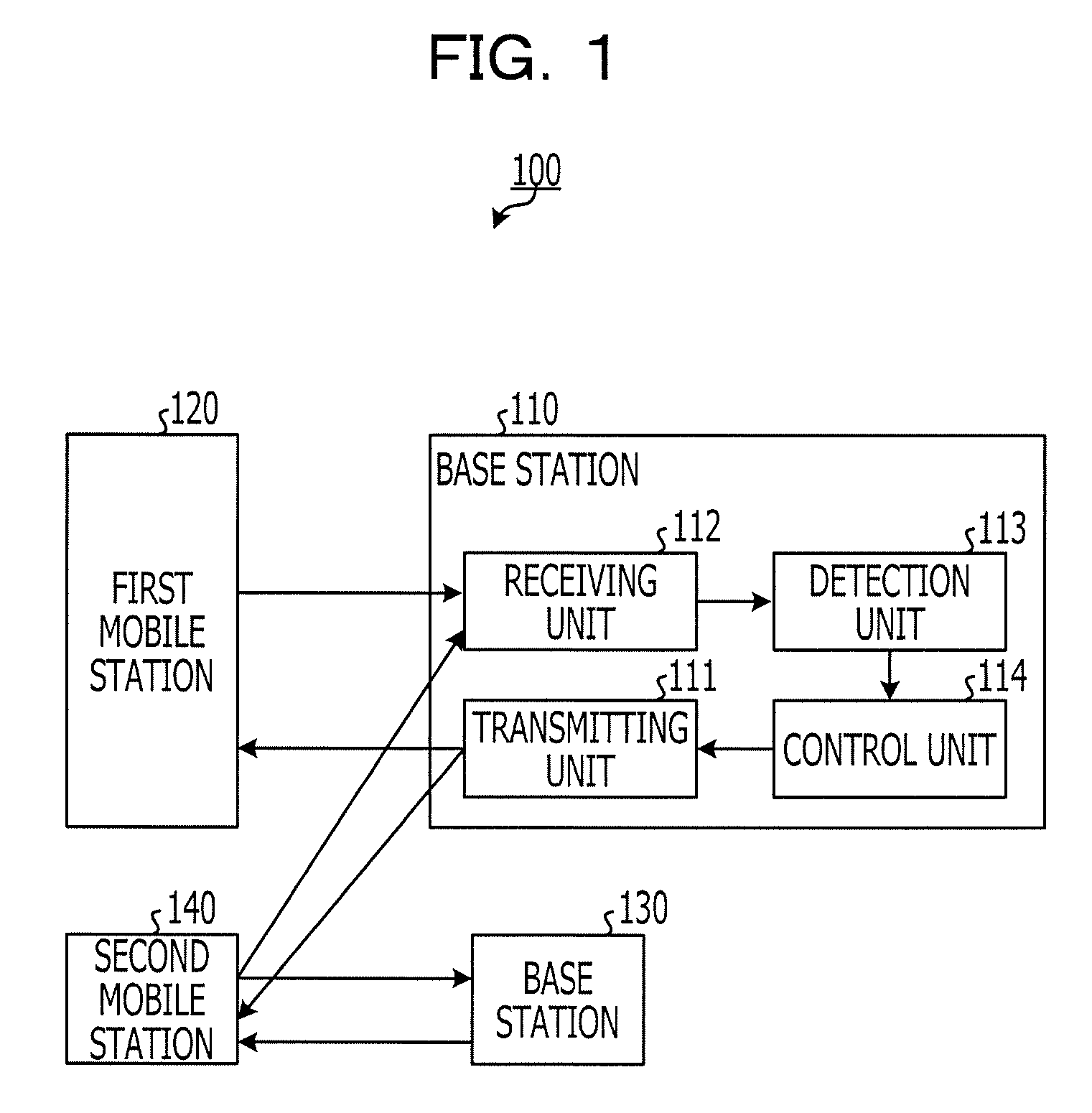
[0026]FIG. 1 is an exemplary view illustrating a configuration of a communication system 100. The communication system 100 includes a base station 110, a first mobile station 120, a base station 130, and a second mobile station 140. The base station 110 performs radio communications with the first mobile station 120. This first mobile station 120 may include either a single or a plurality of mobile stations. The base station 130 performs radio communications with the second mobile station 140. This second mobile station 140 may include either a single or a plurality of mobile stations.

[0027]The radio communications between the second mobile station 140 and the base station 130 are interfered with by a radio signal transmitted from the base station 110 to the first mobile station 120. For example, the radio communications between the second mobile station 140 and the base station 130 use a frequency band that is the same as that of the radio communications between the base station 11...

second embodiment

[0100]A second embodiment will be described by focusing on different part from the first embodiment.

[0101](State Transition of Femto Base Station)

[0102]FIG. 9 is another exemplary state transition dialogue of the femto base station 330. It is to be noted that in FIG. 9, portions corresponding to those in FIG. 7 are given the same reference numerals, and a detailed description thereof will be omitted. The femto base station 330 according to the second embodiment is configured to periodically make the transition from the high transmission power state 610 to the transmission power shutdown state 630, as indicated by an arrow 812 in FIG. 9.

[0103]For example, an interval between timings at which the femto base station 330 makes the transition from the high transmission power state 610 to the transmission power shutdown state 630 is set to be coprime to a period during which the macro UE 320 will perform communications. This setting increases a possibility that the macro UE 320 is amid th...

third embodiment

[0110]A third embodiment will be described by focusing on different part from the first embodiment.

[0111](State Transition of Femto Base Station)

[0112]FIG. 11 is further another exemplary state transition dialogue of the femto base station 330. It is to be noted that in FIG. 11, portions corresponding to those in FIG. 7 are given the same reference numerals, and a detailed description thereof will be omitted. As illustrated in FIG. 11, the femto base station 330 makes the transition among the high transmission power state 610, the low transmission power state 620, the transmission power shutdown states 630, and a transmission power shutdown state 1010.

[0113]The transmission power shutdown state 1010 corresponds to the above-described third state, similar to the transmission power shutdown state 630. The transmission power of the femto base station 330 in the low transmission power state 620 is set to P_L+Poff, where Poff denotes offset power.

[0114]When a victim UE has not consecutiv...


PUM


Abstract

A base station including: a transmitter configured to transmit a first radio signal to a first mobile station, a receiver configured to receive a second radio signal, a processor configured to detect a second mobile station communicates with a communication device differing from the base station, based on a third radio signal from the second mobile station which is contained in the second radio signal, the first radio signal interfering with a radio communication between the second mobile station and the communication device, and to decrease transmission power of the first radio signal, on detecting the second mobile station or failing to detect the second mobile station over a first given period or longer.

Description

CROSS-REFERENCE TO RELATED APPLICATION[0001]This application is based upon and claims the benefit of priority of the prior Japanese Patent Application No. 2012-013521, filed on Jan. 25, 2012, the entire contents of which are incorporated herein by reference.FIELD[0002]The embodiments discussed herein are related to a base station, a communication system, and a communication method.BACKGROUND[0003]Services are provided in which a femto base station (HeNB (Home eNode B)) creates a femtocell and only contract users are permitted to connect to the femto base station. In such services, there are cases where the femtocell is created within a macro cell created by a macro base station (MeNB (Macro evolutional Node B)).[0004]In the case where a macro UE (MUE (Macro User Equipment)) that is not permitted to connect to a femto base station is present within the femtocell, the SINR (signal to interference and noise ratio) of the macro UE may be deteriorated due to the interference from the fem...

Claims


Application Information

Patent Timeline
IPC IPC(8): H04W52/24H04W52/44
CPCH04W52/243H04W52/244H04W52/44Y02B60/50
Inventor KIMURA, DAI
Owner FUJITSU LTD
Learn More