Supercharge Your Innovation With Domain-Expert AI Agents!

Method for controlling an EUV source

a technology of euv source and control method, which is applied in the direction of photomechanical equipment, instruments, transportation and packaging, etc., can solve the problems of insufficient acquisition of the effects of various elements of the resonant charging circuit, difficulty in actual practice in coordinating the first and second switching times, and significant errors in calculating the second switching tim

Active Publication Date: 2016-09-27
USHIO DENKI KK
View PDF7 Cites 0 Cited by
  • Summary
  • Abstract
  • Description
  • Claims
  • Application Information

AI Technical Summary

Benefits of technology

This patent describes a device that can generate short-wavelength radiation by controlling a radiation source. The device has a user-defined parameter value and a pre-defined second switching time that can be used to determine the second switching time and the firing time. This allows for coordinated operation of the device with the target material and the desired discharge voltage. The method can be performed in isolation from the actual operation of the device, reducing the computing requirement. Additionally, the device can have a signal line to control the radiation source, ensuring optimal synchronization with the target material and the desired radiation emission.

Problems solved by technology

In devices for generating discharge plasmas, it is difficult in actual practice to coordinate the first and second switching times and the firing time in such a way that high repetition frequencies are accompanied by minimal deviations in the amount of radiation emitted by the discharge plasma.
A disadvantage in a procedure of this kind consists in that the effects of various elements of the resonant charging circuit are not sufficiently acquired, if at all, due to the simplifications.
Due to these simplifications, significant errors can occur in calculating the second switching time and firing time which must be corrected subsequently by introducing optimization factors.
In the procedure mentioned above, it is also very difficult or even impossible to determine the relationship between the desired discharge voltage and the second switching time after changes in the topology of the resonant charging circuit.

Method used


Image

  • Method for controlling an EUV source
  • Method for controlling an EUV source
  • Method for controlling an EUV source

Examples


first embodiment

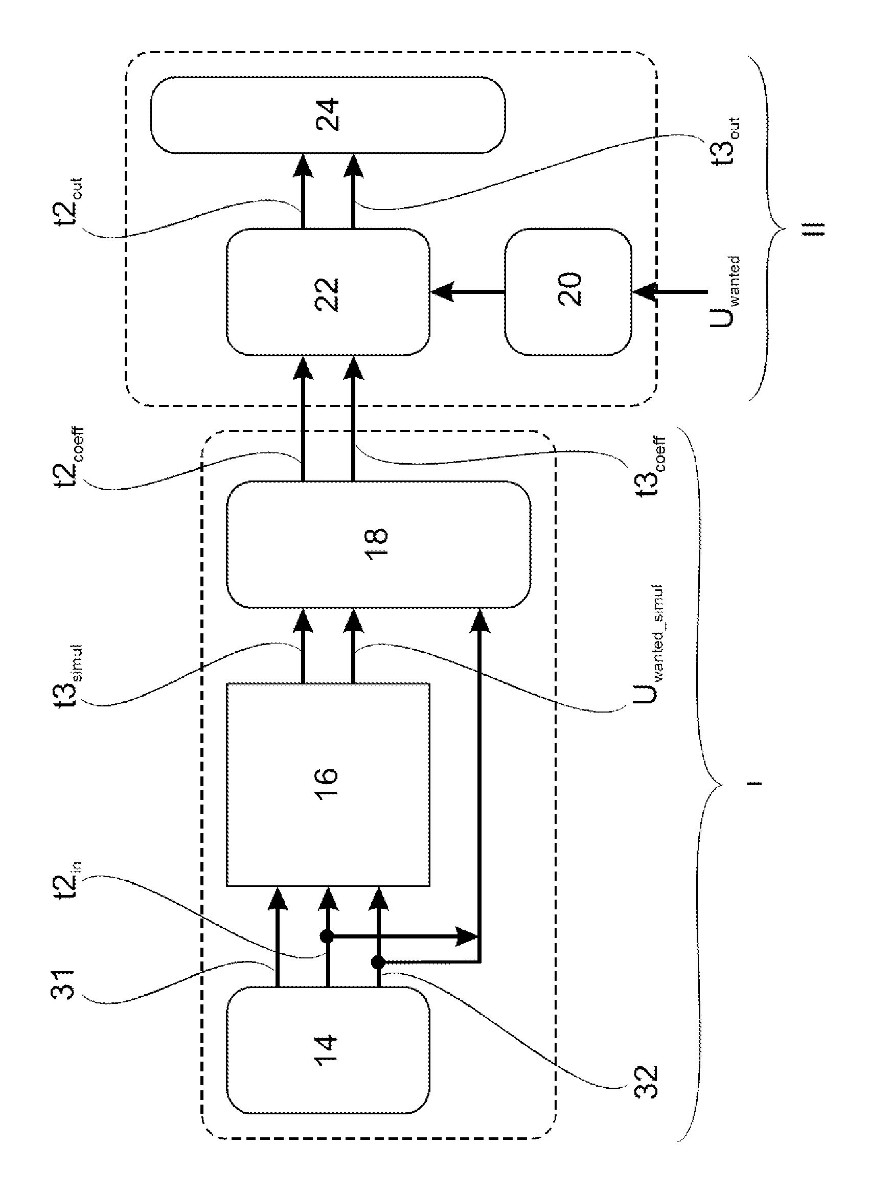
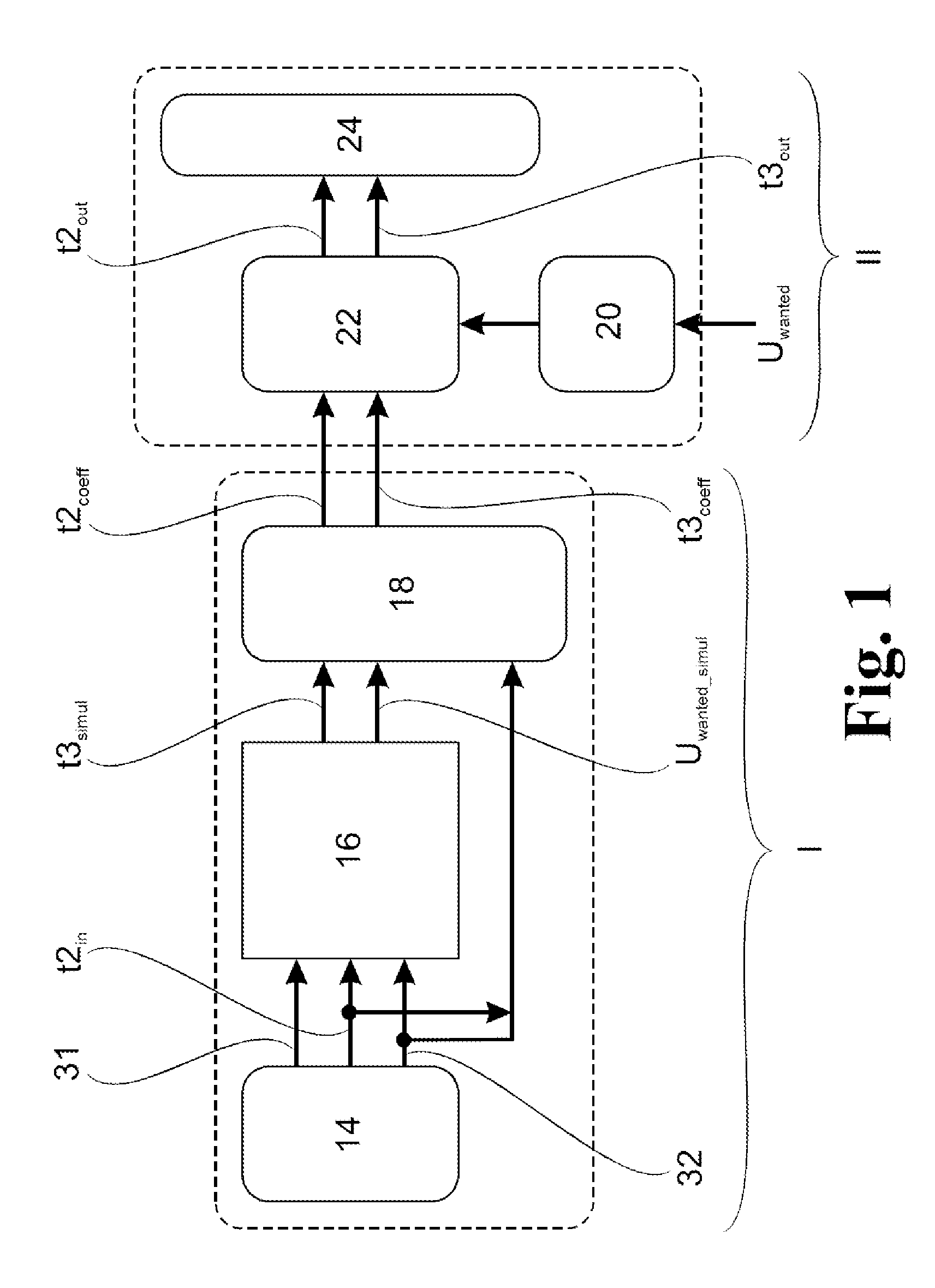
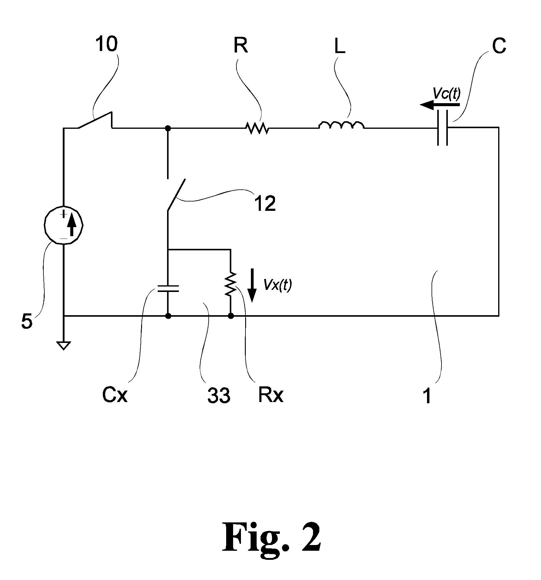
[0068]a device according to the invention for triggering a resonant charging circuit 1 (see FIG. 2) is shown schematically in FIG. 1. The essential elements included in the device are a first input unit 14, a first simulation unit 16, a first regression unit 18, a first measurement value unit 20, a first evaluation unit 22 and a control unit 24.

[0069]The first input unit 14 comprises a storage, a keypad and a screen and allows information to be entered by the user. The information includes input values of which specific parameter values of the resonant charging circuit 1 are a component. The input values are first input parameters 31, second input parameters 32 and a second switching time t2in. The input values are classed by the first input unit 14 and rendered in data formats that can be processed computationally for subsequent elements of the device according to the invention. In further embodiments of the first input unit 14, input can also be carried out via a touch-sensitive s...

third embodiment

[0114]In the method according to the invention, the maximum achievable discharge voltage Umax simul and the associated second switching time t2max simul are determined by means of the device shown in FIG. 9 in the non-time-critical method segment I by the second simulation unit 17. A second coefficient matrix is formed by the second regression unit 19 and is retrievably stored.

[0115]In the time-critical method segment II, actual measurement values of the resonant charging circuit 1 are measured and sent to the second evaluation unit 23 by the second measurement value unit 21. The measurement values are multiplied by the second coefficient matrix, and the discharge voltage Umax calculated which can be achieved based on the actual measurement values is calculated. The calculated discharge voltage Umax calculated is sent to the third comparison unit 29 and compared with the entered desired discharge voltage Uwanted. The discharge voltage having the smaller amount is selected and fed to...


PUM

PropertyMeasurementUnit
time-aaaaaaaaaa
switching timeaaaaaaaaaa
timeaaaaaaaaaa

Abstract

A method for triggering a resonant charging circuit for a device for generating short-wavelength radiation based on discharge plasma is described. Switching times of the resonant charging circuit are determined in a non-time-critical method segment by simulation and are stored to be repeatedly retrievable. Measurement values of the resonant charging circuit are determined in real time in a time-critical method segment. At least one second switching time (t2) at which a discharging switch of the resonant charging circuit is triggered in order to supply at a firing time (t3) a discharge voltage (Uwanted), and the firing time (t3) are calculated. The device has a first input unit, a first simulation unit, a first regression unit, a first measurement value unit, a first evaluation unit and a control unit for triggering a discharging switch of the resonant charging circuit.

Description

RELATED APPLICATIONS[0001]This application claims priority to German Patent Application No. DE 10 2012 113 005.1, filed Dec. 21, 2012, which is incorporated herein by reference in its entirety.FIELD OF THE INVENTION[0002]The invention is directed to a method and a device for triggering a resonant charging circuit for a device for generating short-wavelength radiation based on a discharge plasma which is generated in a pulsed manner.BACKGROUND OF THE INVENTION[0003]A device of this type and use thereof are known in principle from DE 10 2005 045 569 A1.[0004]Devices for generating short-wavelength radiation based on a discharge plasma which is generated in a pulsed manner are used, for example, to implement lithography methods, particularly when it is a question of high repetition frequency of the discharge processes. At the same time, fluctuations in the amount of radiation emitted are to be limited to less than 1% to ensure a consistent quality of the emitted radiation.[0005]The ele...

Claims


Application Information

Patent Timeline
Patent Type & Authority Patents(United States)
IPC IPC(8): H02J7/00H05G2/00H05B41/30G03F7/20
CPCH02J7/0052H02J7/007H02J7/0072H05B41/30H05G2/001G03F7/70033H02J7/00
Inventor EL-HUSSEINI, MOHAMAD HUSSEINPROBST, SVEN WALTER
Owner USHIO DENKI KK
Features
  • R&D
  • Intellectual Property
  • Life Sciences
  • Materials
  • Tech Scout
  • Unparalleled Data Quality
  • Higher Quality Content
  • 60% Fewer Hallucinations
Learn More