Elastic wave filter device and duplexer

a filter device and elastic wave technology, applied in the direction of impedence networks, multiple-port networks, electrical apparatus, etc., can solve the problems of insufficient isolation at the passband, insufficient reception band of the reception filter, insufficient stopband near the passband etc., to suppress the electromagnetic coupling, reduce the number of terminals configured to connect to the ground potential, and reduce the planar shape of the elastic wave filter device

Active Publication Date: 2016-09-27
MURATA MFG CO LTD
View PDF24 Cites 3 Cited by
  • Summary
  • Abstract
  • Description
  • Claims
  • Application Information

AI Technical Summary

Benefits of technology

[0009]Preferred embodiments of the present invention also provide a duplexer that increases out-of-band attenuation at or near a passband of a transmission filter and improves isolation at a reception band.
[0018]A duplexer according to a preferred embodiment of the present invention includes a first filter including the elastic wave filter device according to one of the preferred embodiments of the present invention and a second filter that has a passband different from that of the first filter. In the duplexer according to a preferred embodiment of the present invention, an electromagnetic coupling effect between the first inductor and the second inductor is suppressed in the first filter. Accordingly, the out-of-band attenuation in a vicinity of passband of the first filter is expanded, and the isolation characteristics in a passband of the second filter is improved.

Problems solved by technology

In the configuration described in the Japanese Unexamined Patent Application Publication No. 2010-109694, there is a problem that attenuation at a stopband near a passband of the elastic wave filter, namely, a stopband near a transmission band is not large enough.
Further, in the duplexer, isolation at a passband, namely, a reception band of the reception filter is not sufficient.

Method used


Image

  • Elastic wave filter device and duplexer
  • Elastic wave filter device and duplexer
  • Elastic wave filter device and duplexer

Examples


Embodiment Construction

[0028]Hereinafter the present invention is disclosed in detail by describing specific preferred embodiments of the present invention with reference to the drawings.

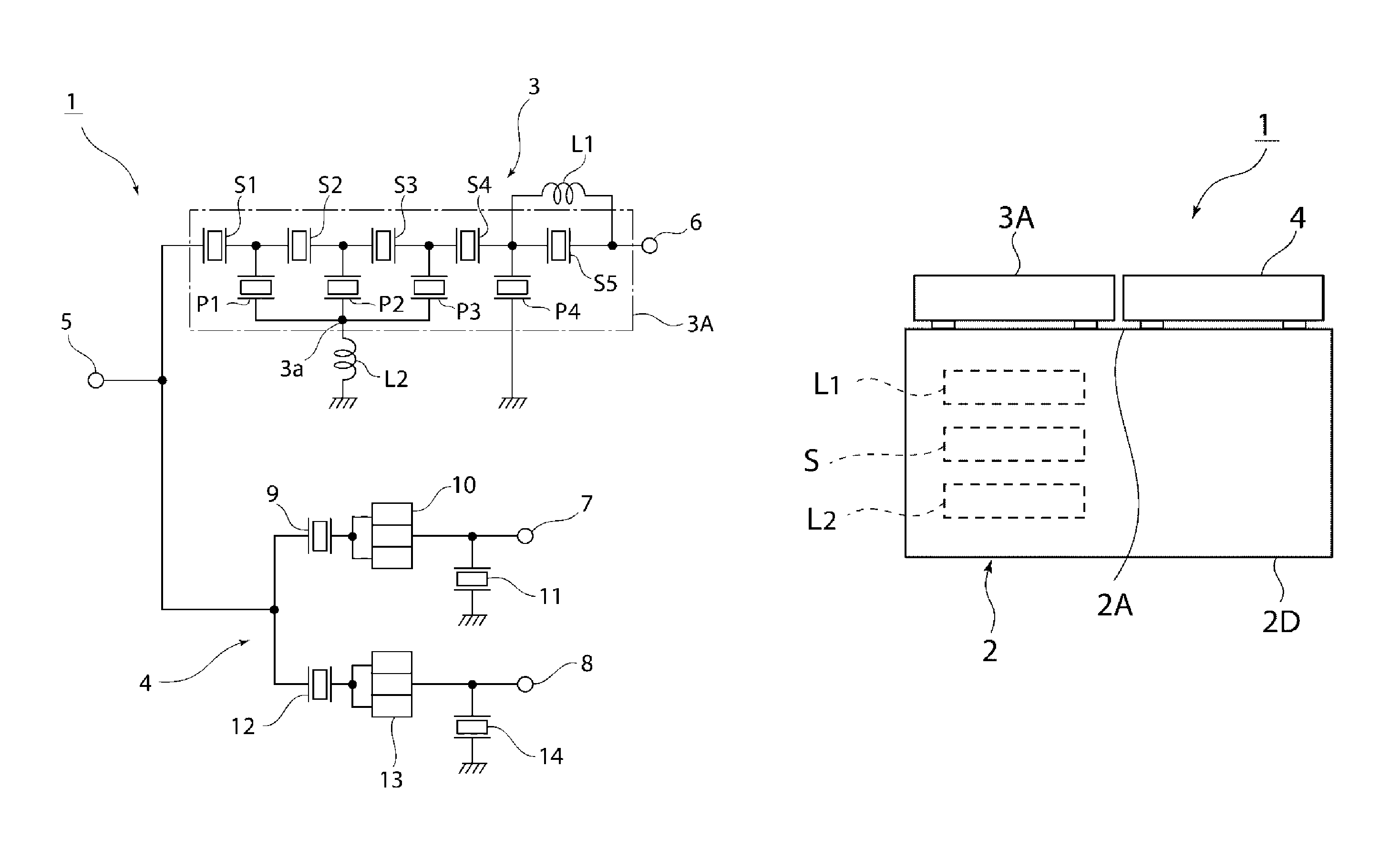
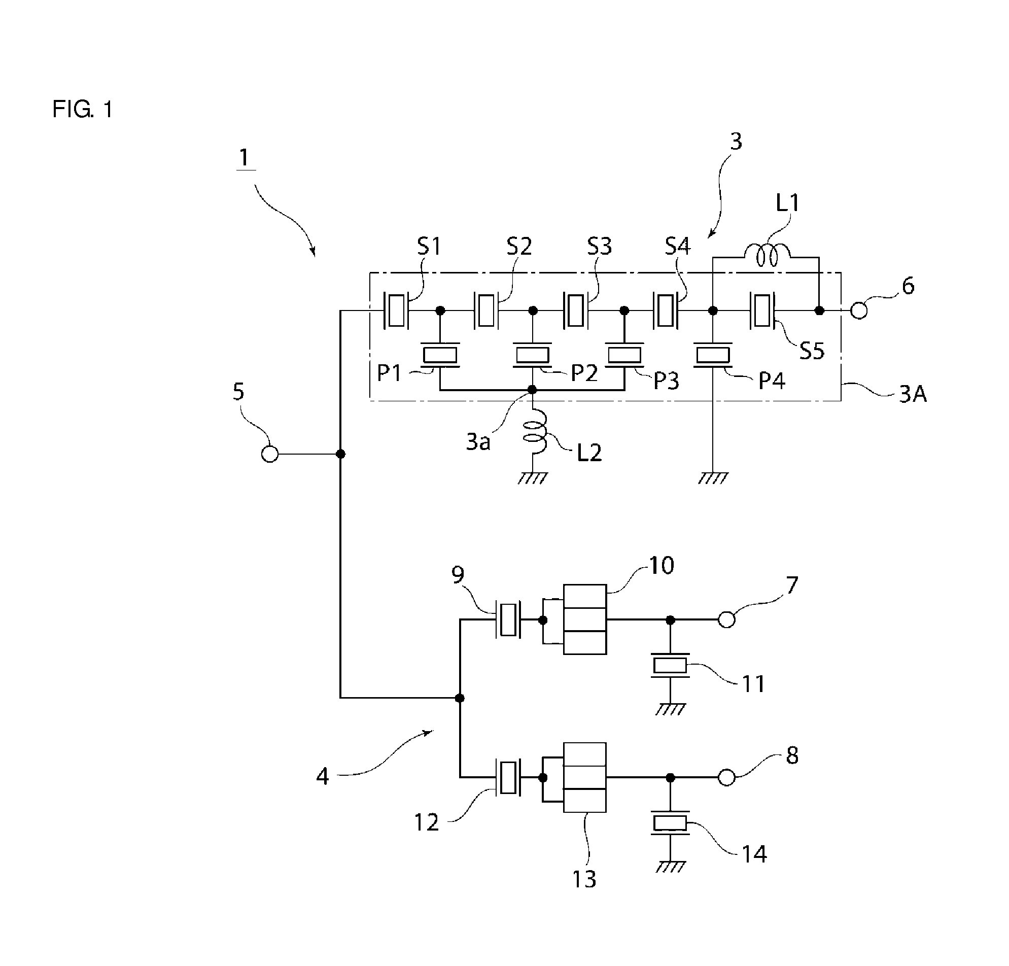
[0029]FIG. 1 is a circuit diagram of a duplexer including an elastic wave filter device according to a preferred embodiment of the present invention.

[0030]In a duplexer 1 of the present preferred embodiment, a transmission filter 3 is provided between an antenna terminal 5 and a transmitter terminal 6. A reception filter 4 is connected between the antenna terminal 5 and first and second receiver terminals 7, 8.

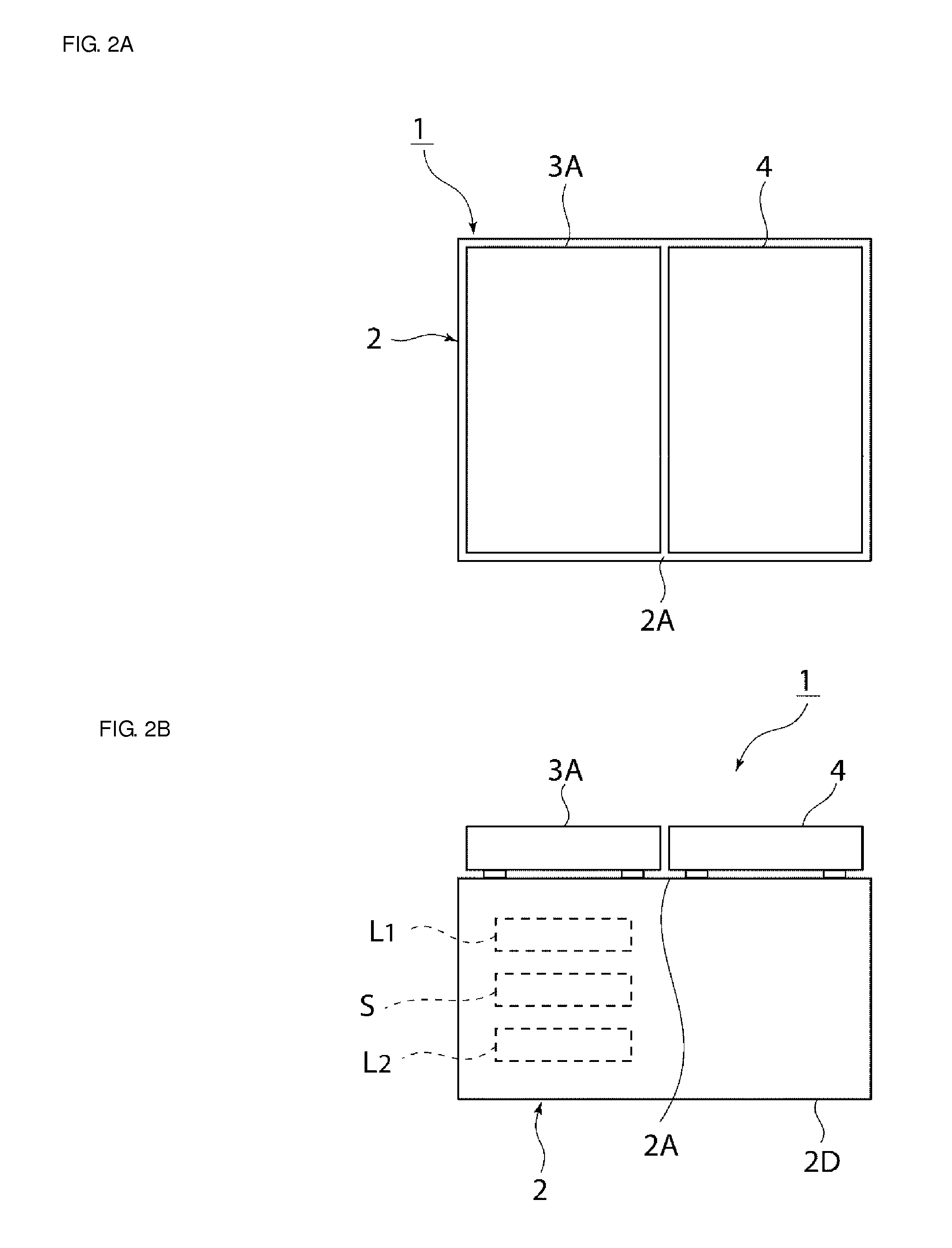
[0031]The transmission filter 3 includes an elastic wave filter element chip 3A having a ladder circuit configuration. In FIG. 1, a portion inside the elastic wave filter element chip 3A is surrounded by a dashed-dotted line. In other words, a plurality of series arm resonators S1 to S5 are connected in series to each other in a series arm connecting the antenna terminal 5 and the transmitter terminal 6. A plurality...


PUM


Abstract

In an elastic wave filter device, an elastic wave filter element chip is mounted on a board. In the elastic wave filter element chip, a ladder filter including a plurality of series arm resonators and a plurality of parallel arm resonators are provided. In / on the board, a first inductor connected in parallel to the series arm resonator and a second inductor connected between the parallel arm resonators P1-P3 and a ground potential are provided. In / on the board, a shield electrode is located between the first inductor and the second inductor.

Description

BACKGROUND OF THE INVENTION[0001]1. Field of the Invention[0002]The present invention relates to elastic wave filter devices having ladder circuit configurations, and more specifically, elastic wave filter devices in which elastic wave filter chips are mounted on boards.[0003]2. Description of the Related Art[0004]Conventionally, elastic wave filters having ladder circuit configurations have been widely used as transmission filters of duplexers in cellular phones. For example, the following Japanese Unexamined Patent Application Publication No. 2010-109694 discloses a duplexer including a transmission filter composed of an elastic wave filter having a ladder circuit configuration and a reception filter composed of a longitudinally coupled resonator-type elastic wave filter.[0005]In the transmission filter of duplexer described in the Japanese Unexamined Patent Application Publication No. 2010-109694, a plurality of series arm resonators is formed in a series arm. A bridging inductan...

Claims


Application Information

Patent Timeline
Patent Type & Authority Patents(United States)
IPC IPC(8): H03H9/72H03H9/56H03H9/60H03H9/25H03H9/70H03H9/64H03H9/24H03H9/54H03H9/05H03H7/46H03H1/00
CPCH03H9/0576H03H9/0566H03H9/24H03H9/25H03H9/542H03H9/568H03H9/605H03H9/6483H03H9/706H03H9/725H03H7/463H03H2001/0085
Inventor KUZUSHITA, TAKUMATANIGUCHI, YASUMASAMIYAKE, TAKASHI
Owner MURATA MFG CO LTD
Why Eureka
Try Eureka