Method of clamping a substrate and clamp preparation unit using capillary clamping force

a substrate and clamping technology, applied in the direction of metal-working holders, positioning apparatuses, supports, etc., can solve the problems of substrate clamping mechanism, unsuitable solution, and ineffective clamping mechanism, and achieve the effect of improving performan

Active Publication Date: 2016-10-04
ASML NETHERLANDS BV
View PDF34 Cites 146 Cited by
  • Summary
  • Abstract
  • Description
  • Claims
  • Application Information

AI Technical Summary

Benefits of technology

[0009]It is an object of the invention to provide a substrate support structure for clamping a substrate on a surface thereof by means of a capillary layer as well as a method of clamping a substrate on a surface of a substrate support structure with improved performance. This object has been achieved by providing a method of clamping a substrate on a surface of a substrate support structure, the method comprising applying a liquid on a surface of the substrate support structure, the surface being provided with a plurality of contact elements, so that the liquid forms a layer covering the contact elements; providing the substrate and placing the substrate onto the liquid layer; and removing a portion of the liquid from under the substrate so that the substrate rests on the plurality of contact elements and is clamped by means of a capillary clamping force exerted by a capillary layer of the liquid between the substrate and the surface of the substrate support structure.

Problems solved by technology

However, if aforementioned position control is required in a vacuum environment, such a clamping mechanism will not be effective.
It will be understood that such a solution is not very suitable for use in combination with one or more beams of charged particles like electrons and / or ions.
Under some special circumstances, the substrate clamping mechanism described in WO2009 / 011574 does not perform in an optimal manner, e.g. due to the presence of voids in the capillary layer.
Furthermore, due to evaporation processes, the capillary layer will be present for a limited period of time.
As a result, the clamping mechanism may only be useful for a selection of devices to be patterned.

Method used


Image

  • Method of clamping a substrate and clamp preparation unit using capillary clamping force
  • Method of clamping a substrate and clamp preparation unit using capillary clamping force
  • Method of clamping a substrate and clamp preparation unit using capillary clamping force

Examples


first embodiment

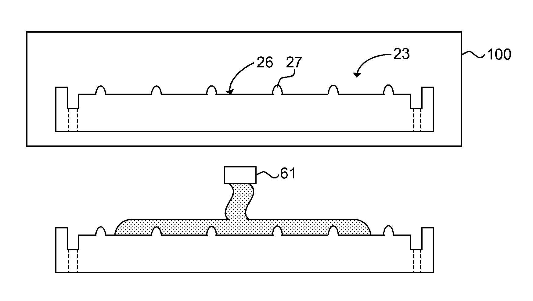
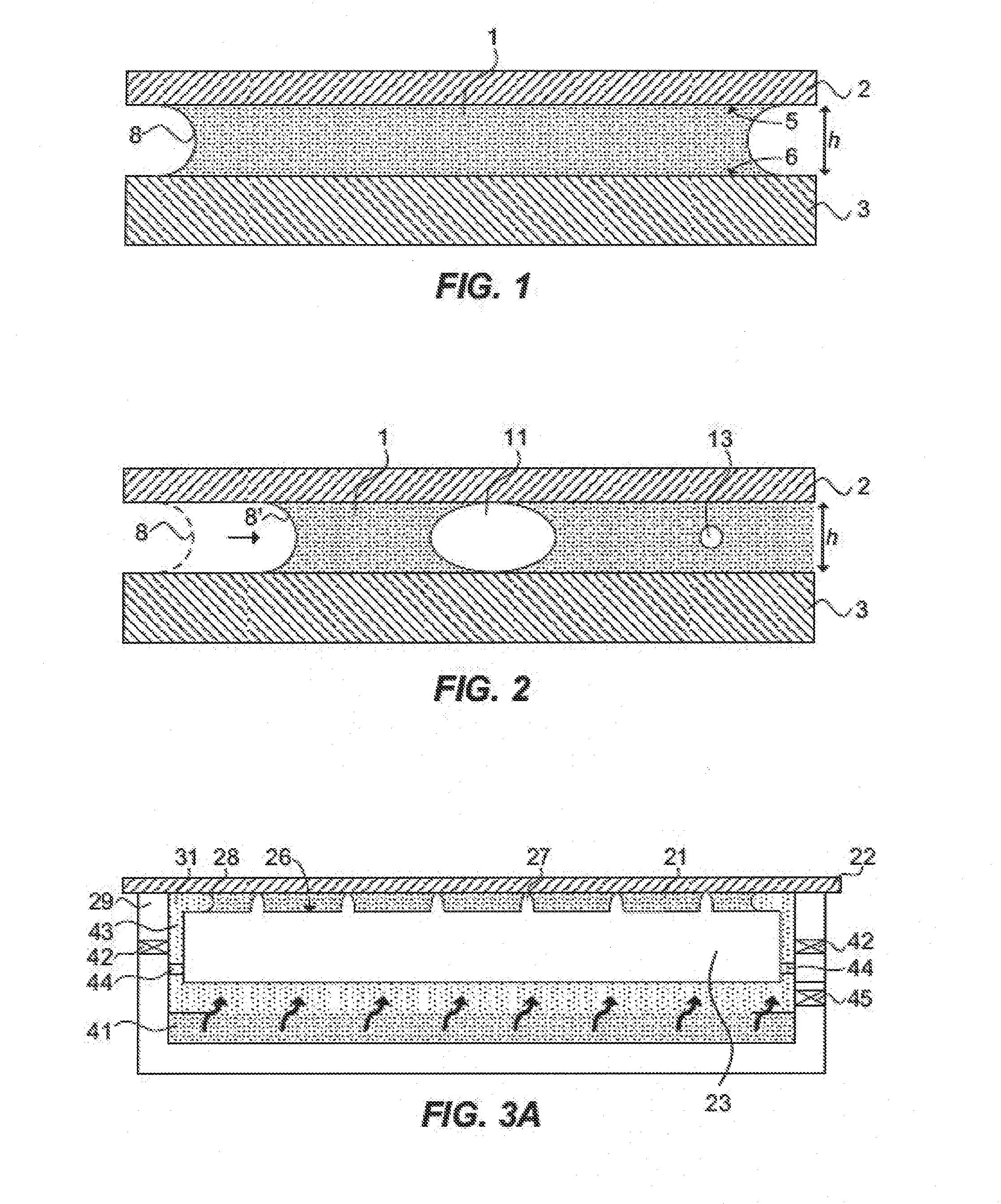
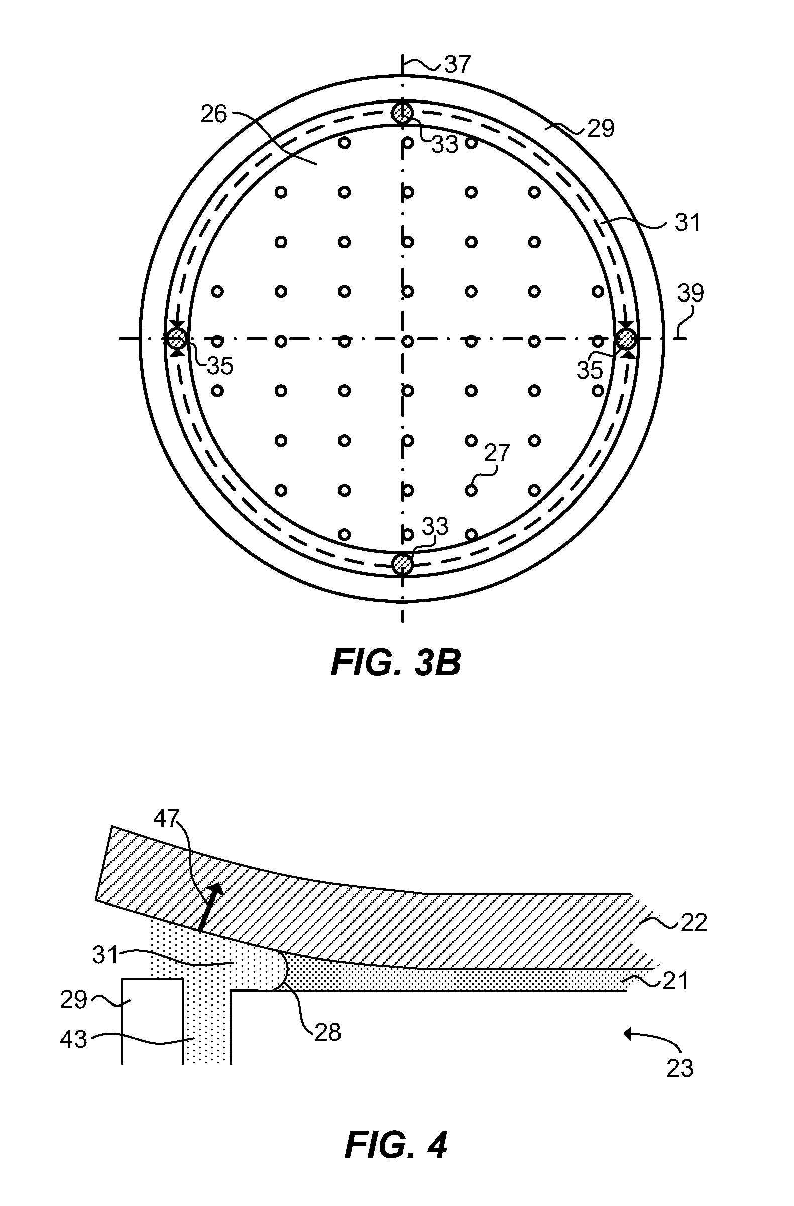
[0037]FIGS. 3A and 3B are a sectional view and a top view of a substrate support structure 23 supporting a substrate according to the invention respectively. The support structure is equipped to clamp a substrate 22 by means of a capillary layer 21. The surface 26 of the substrate support structure 23 is provided with a plurality of contact elements 27 in the form of burls. The substrate support structure 23 further comprises a sealing structure 29 and a liquid removal system.

[0038]In addition to or instead of using burls as contact elements 27, a plurality of spacers, e.g. glass grains, SiO2 grains or the like may be dispersed uniformly over the surface 26 of the substrate support structure 23. The presence of contact elements like burls may reduce the influence of contamination by particles on the backside of the substrate 22. Furthermore, the contact elements serve the purpose of keeping the substrate 22 substantially flat by withstanding the clamping force of the capillary layer...

second embodiment

[0054]FIG. 5 is a sectional view of a substrate support structure 23 supporting a substrate 22 according to the invention. The embodiment of the substrate support structure 23 of FIG. 5 further comprises a circumferential rim 51. The circumferential rim 51 provides a smaller distance between the substrate support structure 23 and the substrate 22. While the nominal distance between the substrate support structure 23 and the substrate 22, in FIGS. 1 and 2 referred to as height h, typically is about 3-10 microns, the distance between the circumferential rim 51 and the substrate 22 typically would lie in the range of 500 nm to 1.5 microns. Preferably, the circumferential rim 51 has a height being less than 1 micron smaller than the nominal height of contact elements provided on the surface 26 of the substrate support structure 23.

[0055]Without wishing to being bound by theory, the circumferential rim 51 is believed to limit substrate peeling in a way described with reference to FIGS. 6...

third embodiment

[0075]FIG. 8 schematically shows a top view of a substrate support structure 83 according to the invention. The substrate support structure 83 comprises a surface 86 for clamping a substrate. Preferably, the surface is provided with contact elements 87. Additionally, the substrate support structure comprises a gas distribution system including a moat 91, gas inlets 93, and gas outlets 95. Functions of these components have been discussed with reference to FIG. 3A and equally apply for this embodiment. The substrate support structure 83 may be used in embodiments of the method of clamping in a similar way as discussed with respect to substrate support structure 23 with reference to FIGS. 7A-7J.

[0076]In contrast to embodiments of the substrate support structure 23 shown in FIGS. 3A and 5, substrate support structure 83 comprises a surface 86 which is divided in a plurality of sub-surfaces. The sub-surfaces may take the form of tiles, for example of hexagonal shape, and be arranged in ...


PUM

PropertyMeasurementUnit
acute angleaaaaaaaaaa
diameteraaaaaaaaaa
heightaaaaaaaaaa

Abstract

The invention relates to a method of clamping a substrate on a surface of a substrate support structure. First, a liquid is applied on a surface of the substrate support structure. The surface is provided with a plurality of contact elements. The liquid is applied such that the contact elements are fully covered by a liquid layer. Then the substrate is provided and placed onto the liquid layer. Finally, liquid underneath the substrate is removed such that the substrate rests on the plurality of contact elements and is clamped by means of a capillary clamping force exerted by a capillary layer of the liquid between the substrate and the surface of the substrate support structure.

Description

CROSS REFERENCE TO RELATED APPLICATIONS[0001]This application claims priority to U.S. provisional application No. 61 / 154,411 filed on Feb. 22, 2009, and British application No. GB 0905786.0 filed on Apr. 3, 2009. Both applications are hereby incorporated by reference in their entirety.BACKGROUND OF THE INVENTION[0002]1. Field of the Invention[0003]The present invention relates to a method of clamping a substrate on a surface of a substrate support structure, a clamp preparation unit configured to clamp a substrate to a substrate support structure, and a lithography system comprising such a clamp preparation unit.[0004]2. Description of the Related Art[0005]Clamping of a substrate, for example a wafer, onto a surface of a substrate support structure, for example a wafer table, is well known in the semiconductor industry, and in particular in lithography systems. In such lithography systems, the clamped substrate is to be patterned by means of subjection to incident photons or charged...

Claims


Application Information

Patent Timeline
Patent Type & Authority Patents(United States)
IPC IPC(8): H01L21/687G03F7/20H01L21/683
CPCH01L21/6875G03F7/707H01L21/6838Y10T29/49815Y10T29/49998Y10T29/53H01L21/67173H01L21/67706H01L21/67724H01L21/67748H01L21/6776H01L21/67778H01L21/683H01L21/687H01L21/68714H01L21/0273H01L21/68735H01L21/68707H01L21/68742H01L21/68785
Inventor DE JONG, HENDRIK JANWIELAND, MARCO JAN-JACO
Owner ASML NETHERLANDS BV
Why Eureka
Try Eureka