Hydraulic percussion apparatus and method of use
a technology of hydraulic percussion and percussion, which is applied in the direction of vibration drilling, drilling machines and methods, percussion drilling, etc., can solve the problems of hard and brittle, ineffective rotation of the drill bit alone, and difficulty in drilling, so as to reduce friction
- Summary
- Abstract
- Description
- Claims
- Application Information
AI Technical Summary
Benefits of technology
Problems solved by technology
Method used
Image
Examples
second embodiment
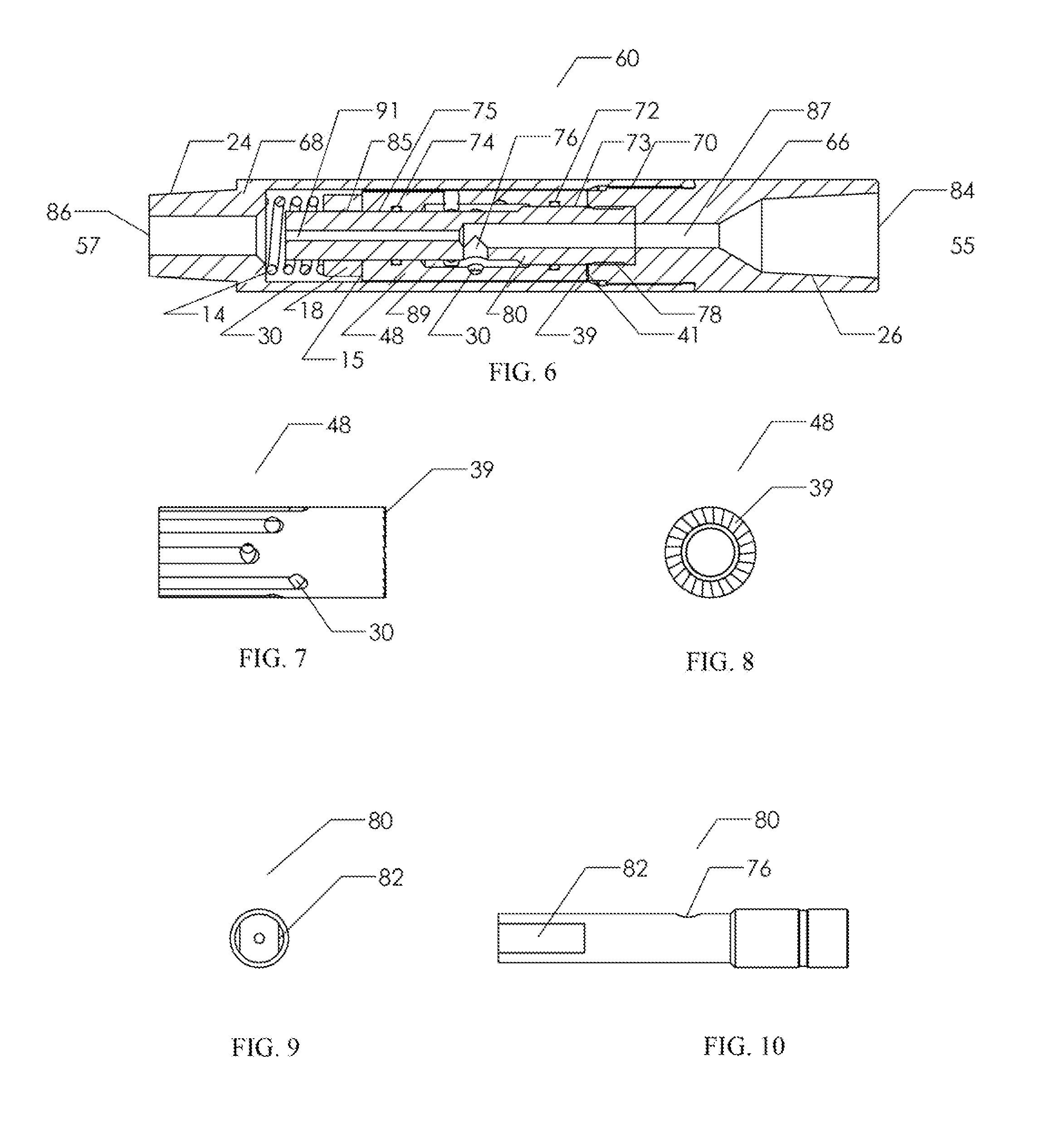
[0048]FIG. 6 shows the hydraulic percussive apparatus (60) of the present invention utilized to provide upward percussive or hammering forces to a pipe string having a central bore through which fluid may be introduced. The apparatus (60) has an upper end (55) and a lower end (57) and is configured for threadable attachment to the pipe string when deployed in a wellbore.
[0049]Apparatus (60) is comprised of a top sub (66) and a tubular housing (68) that is threaded on its radial surfaces where it may be threadedly attached to a tubular housing (68) by means of threaded connection (70). Positioned within the housing (68) is a rotatably mounted longitudinally extending rotor (48), a thrust bearing (18), a mandrel (80), and a spring (14). Housing (68) and rotor (48) are illustrated as a single components but may consist of a multitude of individual parts connected together possibly by one or more of several means such as threaded connections, splines, keyways, welding, brazing, press or...
first embodiment
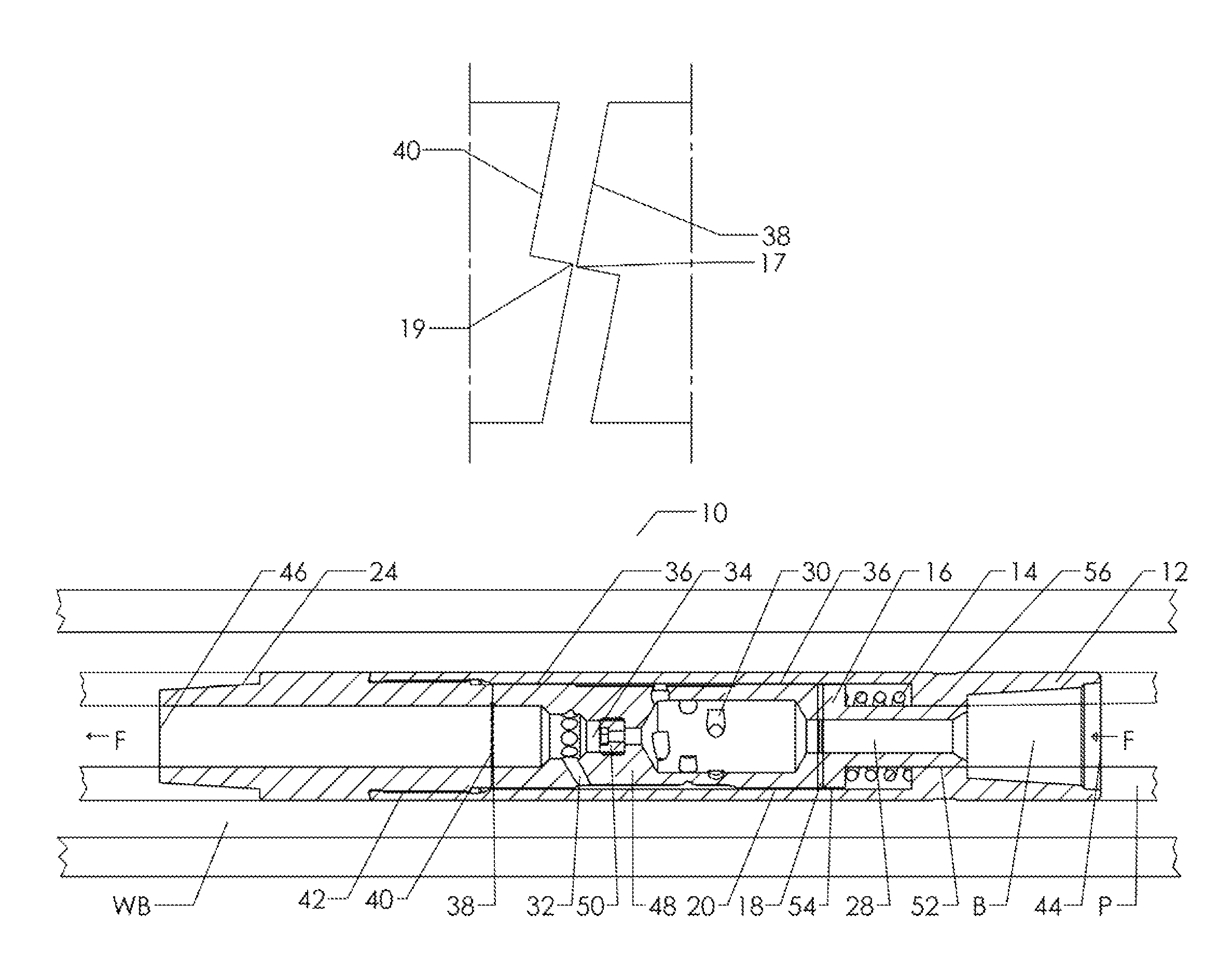
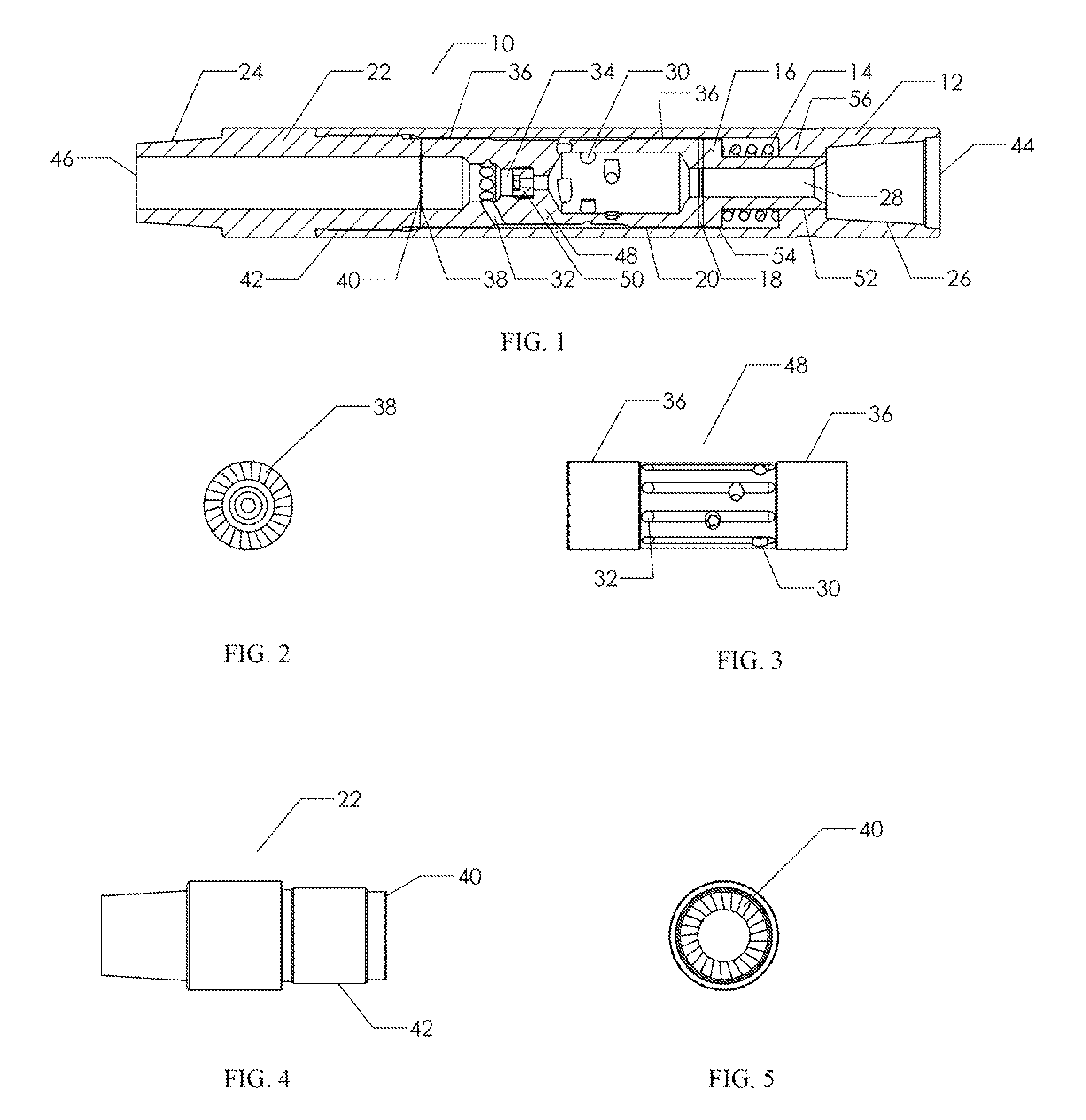
[0053]Profiled surfaces (39) and (41) may have the same configuration as profiled surfaces (38) and (39) of the The features of profiled surfaces (38), (39), (40), and (41) are shown as having saw-tooth profiles but these profiled surface features may be of any suitable form such as waveform, sinusoidal, or other irregular profiled surface. The features of profiled surfaces (38), (39), (40), and (41) are also shown to be of the same size and shape, and are uniform around the entire area circumference of the interfacing profiled surfaces but the features of the profiled surfaces (38), (39), (40), and (41) may be non-uniform and of differing size and shape.
[0054]The thrust bearing (18) is positioned within the housing (68) between spring (14) and the rotor (48) and is shown as a thrust sleeve for simplicity and clarity of illustration but the thrust bearing (18) can be of many forms such as those mentioned when discussing the thrust bearing of the embodiment shown in FIG. 1. Thrust b...
PUM
 Abstract
Description
Claims
Application Information
 - R&D
- Intellectual Property
- Life Sciences
- Materials
- Tech Scout
- Unparalleled Data Quality
- Higher Quality Content
- 60% Fewer Hallucinations
Browse by: Latest US Patents, China's latest patents, Technical Efficacy Thesaurus, Application Domain, Technology Topic, Popular Technical Reports.
© 2025 PatSnap. All rights reserved.Legal|Privacy policy|Modern Slavery Act Transparency Statement|Sitemap|About US| Contact US: help@patsnap.com


