Branch circuit and branch cable
a branch circuit and branch cable technology, applied in the direction of electrical equipment, multiple-port networks, network topologies, etc., can solve the problems of inability to use circuit configuration in which signals are separated into respective frequency bands, and difficulty in providing many antenna devices for respective frequency bands, so as to avoid undesired resonance and avoid unfavorable branching characteristics
- Summary
- Abstract
- Description
- Claims
- Application Information
AI Technical Summary
Benefits of technology
Problems solved by technology
Method used
Image
Examples
first preferred embodiment
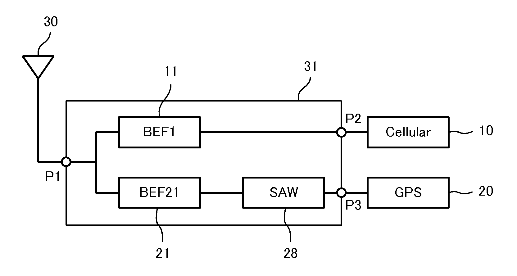
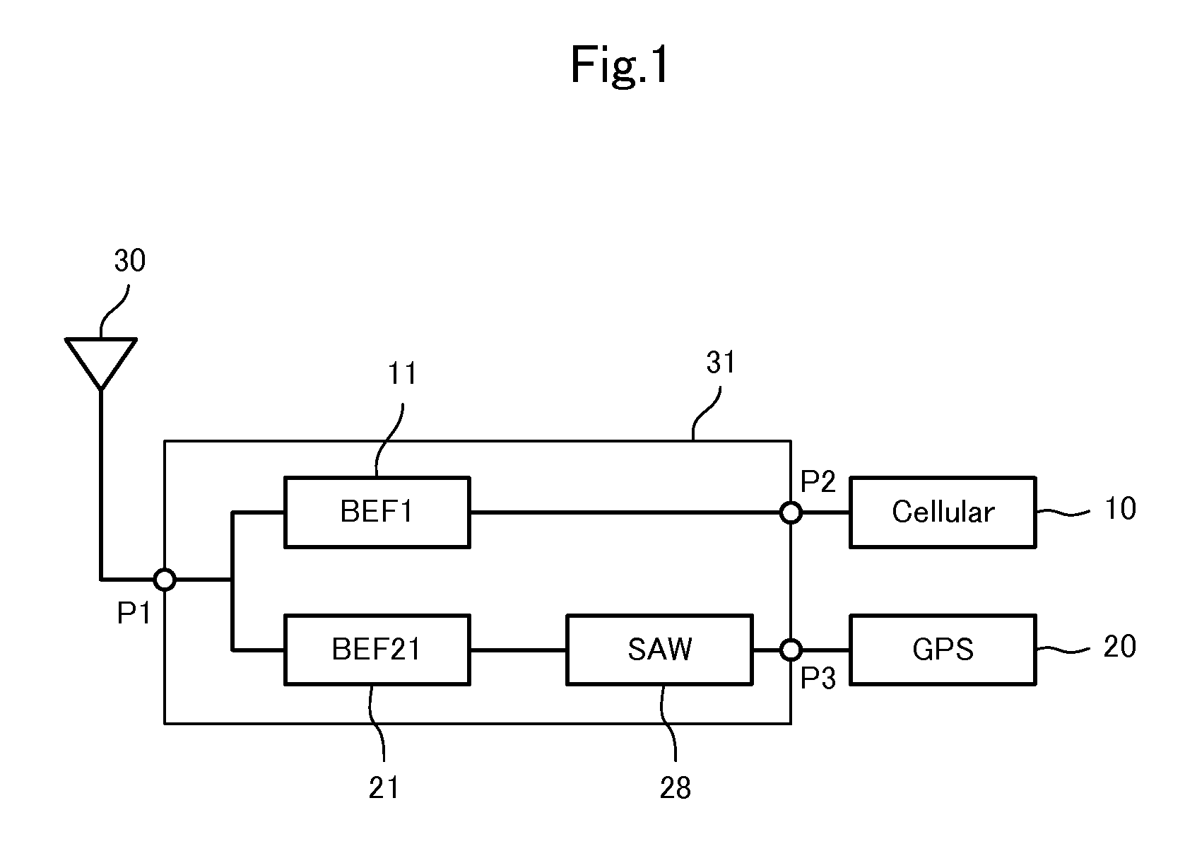
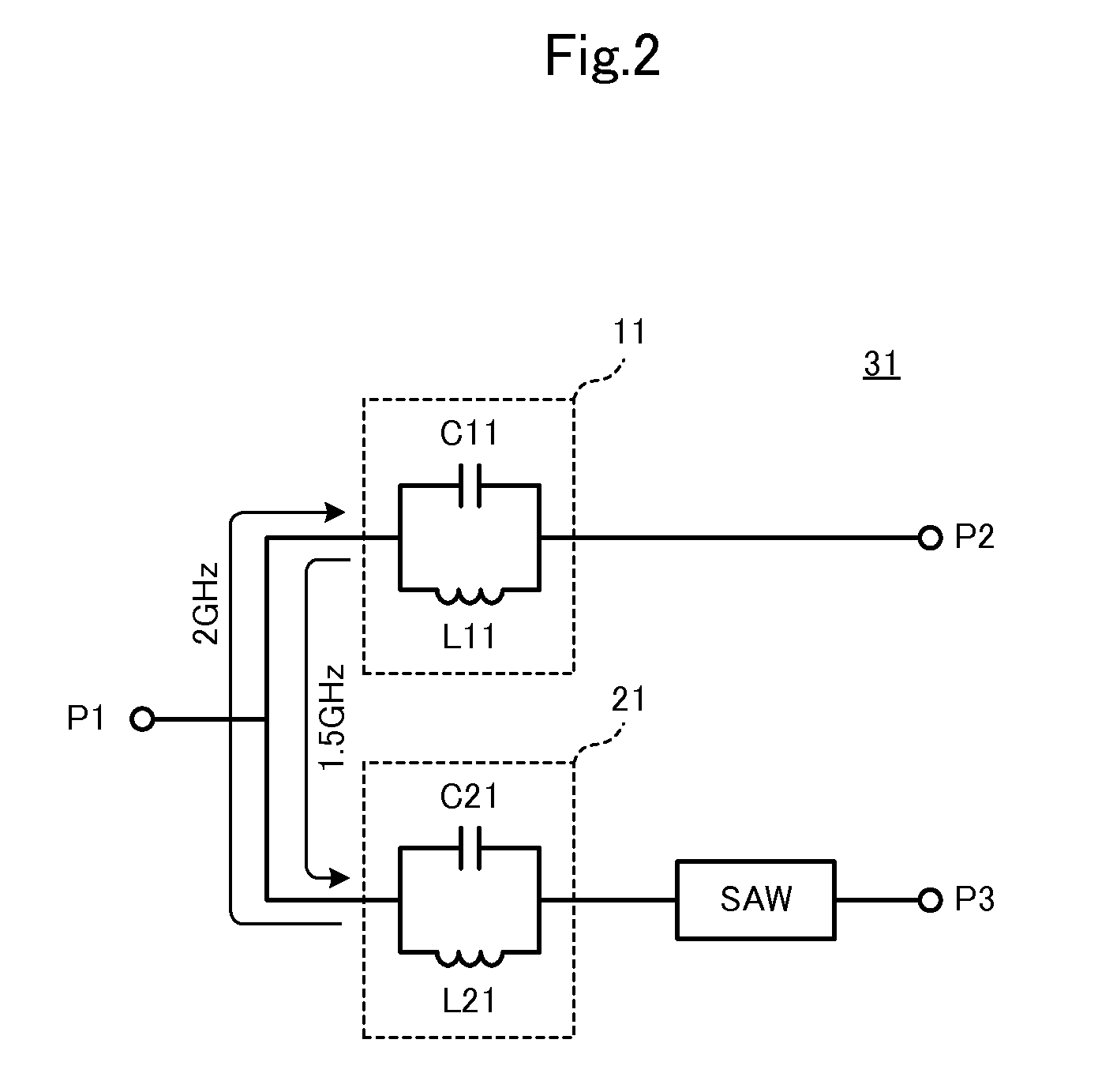
[0060]FIG. 1 is a block diagram of a communication apparatus including a branch circuit according to a first preferred embodiment of the present invention. The communication apparatus includes a branch circuit 31. The branch circuit 31, which includes a common antenna port P1, is a branch circuit that is configured to separate a first communication signal (cellular signal), which includes a signal in a low band and a signal in a high band, and a second communication signal (GPS signal) which is a signal in a frequency band between the low band and the high band. Hereinafter, the “first communication signal” is called a “cellular signal” and the “second communication signal” is called a “GPS signal”.
[0061]In this example, the frequency bands preferably are as follows:
[0062]Low band (800 MHz band: 704 MHz to 960 MHz)
[0063]High band (2.2 GHz band: 1710 MHz to 2690 MHz)
[0064]GPS signal (1.5 GHz band: 1574 MHz to 1606 MHz)
[0065]An antenna 30 is connected to the antenna port P1 of the bra...
second preferred embodiment
[0071]FIG. 4 is a circuit diagram of a branch circuit 32 according to a second preferred embodiment of the present invention. The branch circuit 32 includes an antenna port P1, a cellular signal port P2 and a GPS signal port P3. The branch circuit 32 separates a first communication signal (cellular signal), which includes a signal in a low band and a signal in a high band, and a second communication signal (GPS signal), which is a signal in a frequency band between the low band and the high band.
[0072]Two cellular-signal-line-side band elimination filters 11 and 12 are provided on a cellular signal line. A SAW filter 28, a GPS-signal-line-side band elimination filter 21, and a band pass filter 24 are provided on a GPS signal line. The band pass filter 24 is provided between the GPS-signal-line-side band elimination filter 21 and the SAW filter 28. A capacitor C5 is provided between the band pass filter 24 and the SAW filter 28. A low-noise amplifier (LNA) 29 is provided in a stage s...
third preferred embodiment
[0080]FIG. 8 is a block diagram of a communication apparatus including a branch circuit 33 according to a third preferred embodiment of the present invention. The branch circuit 33 includes an antenna port P1, a cellular signal port P2, and a GPS signal port P3. The branch circuit 33 separates a first communication signal (cellular signal), which includes a signal in a low band and a signal in a high band, and a second communication signal (GPS signal), which is a signal in a frequency band between the low band and the high band.
[0081]An antenna 30 is connected to the antenna port P1 of the branch circuit 33. A communication circuit 10 for cellular signals is connected to the cellular signal port P2 of the branch circuit 33, and a GPS receiver circuit 20 is connected to the GPS signal port P3 of the branch circuit 33.
[0082]Unlike the branch circuit 31 illustrated in FIG. 1, two GPS-signal-line-side band elimination filters 21 and 22 are provided on a GPS signal line. Further, an LNA...
PUM
 Abstract
Description
Claims
Application Information
 - R&D
- Intellectual Property
- Life Sciences
- Materials
- Tech Scout
- Unparalleled Data Quality
- Higher Quality Content
- 60% Fewer Hallucinations
Browse by: Latest US Patents, China's latest patents, Technical Efficacy Thesaurus, Application Domain, Technology Topic, Popular Technical Reports.
© 2025 PatSnap. All rights reserved.Legal|Privacy policy|Modern Slavery Act Transparency Statement|Sitemap|About US| Contact US: help@patsnap.com


