Branch circuit and branch cable

a branch circuit and branch cable technology, applied in the direction of electrical equipment, multiple-port networks, network topologies, etc., can solve the problems of inability to use circuit configuration in which signals are separated into respective frequency bands, and difficulty in providing many antenna devices for respective frequency bands, so as to avoid undesired resonance and avoid unfavorable branching characteristics

Active Publication Date: 2015-04-02
MURATA MFG CO LTD
View PDF1 Cites 18 Cited by
  • Summary
  • Abstract
  • Description
  • Claims
  • Application Information

AI Technical Summary

Benefits of technology

[0013]Preferred embodiments of the present invention provide a branch circuit and a branch cable that realize satisfactory branching characteristics by avoiding undesirable resonance generated by a SAW filter and a band elimination filter provided on two communication signal lines.
[0016]With this configuration, the loss of the first communication signal due to the attenuation band of the SAW filter being on the short-circuit impedance side is avoided, such that favorable branching characteristics are realized.
[0018]It is preferable that the second-communication-signal-line-side band elimination filter is a band elimination filter configured to reflect a signal in the low band and a band elimination filter configured to reflect a signal in the high band. With this configuration, in the second-communication-signal-line-side band elimination filter, a communication signal in the high band and a communication signal in the low band are both reflected to the antenna side and the first-communication-signal-line side, such that the branching characteristics are enhanced.
[0024]With this configuration, an antenna port preferably is connected to the input / output ports of two communication circuits and, at the same time, separation in accordance with frequency bands is performed. Hence, there is no need to provide a branch circuit on a circuit substrate, resulting in a reduction in the size of and space occupied by an apparatus.
[0025]It is preferable that each of the first-communication-signal-line-side band elimination filter and the second-communication-signal-line-side band elimination filter include a parallel circuit including an inductor and a capacitor, and the inductor and the capacitor include the signal conductors and ground conductors provided on the dielectric element bodies. With this configuration, there is no need to mount individual components of the first-communication-signal-line-side band elimination filter and the second-communication-signal-line-side band elimination filter, resulting in easy reduction in thickness and high mass production capability.
[0028]According to various preferred embodiments of the present invention, favorable branching characteristics are realized by avoiding undesired resonance due to the SAW filter and the first-communication-signal-line-side band elimination filter. Further, the branch circuit preferably is integrated into a small space within a casing.

Problems solved by technology

Hence, it is difficult to provide many antenna devices for respective frequency bands, and it becomes important to share an antenna and provide a branch circuit for branching antenna signals to a plurality of communication circuits.
However, the existing signal separation circuit illustrated in FIG. 25 is a so-called triplexer, which only branches signals in three frequency bands to respective three input / output units and, hence, such a circuit configuration in which signals are separated into respective frequency bands cannot be used.
However, a branch circuit having the configuration illustrated in FIG. 26 has the following problems.

Method used


Image

  • Branch circuit and branch cable
  • Branch circuit and branch cable
  • Branch circuit and branch cable

Examples


first preferred embodiment

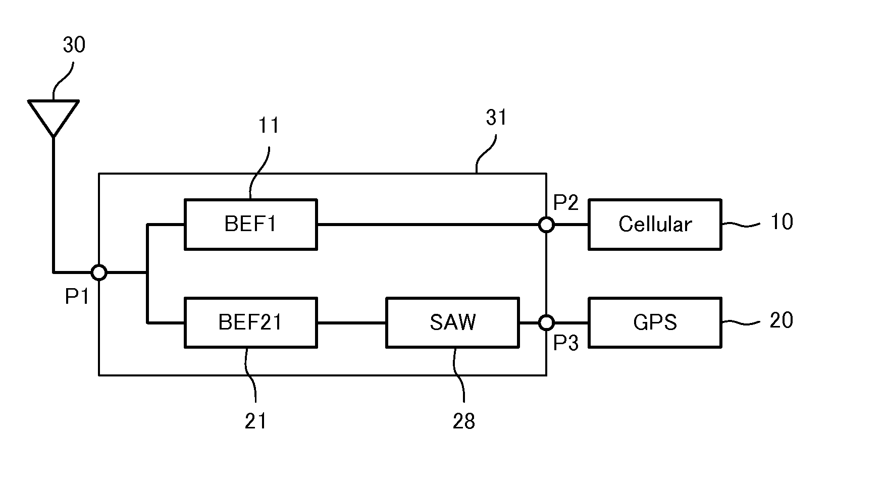
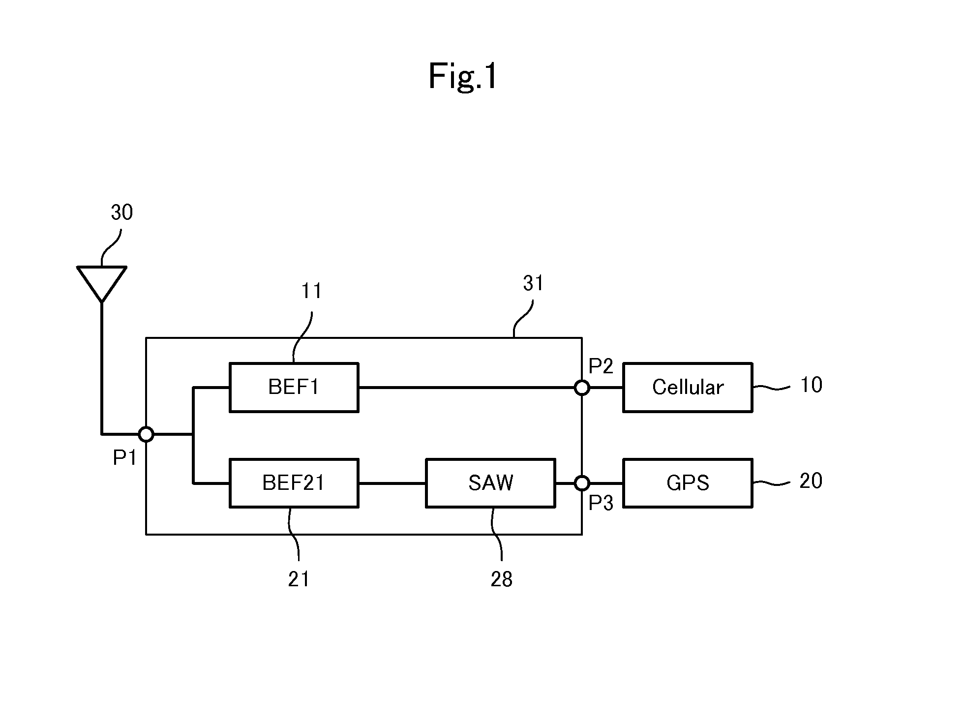
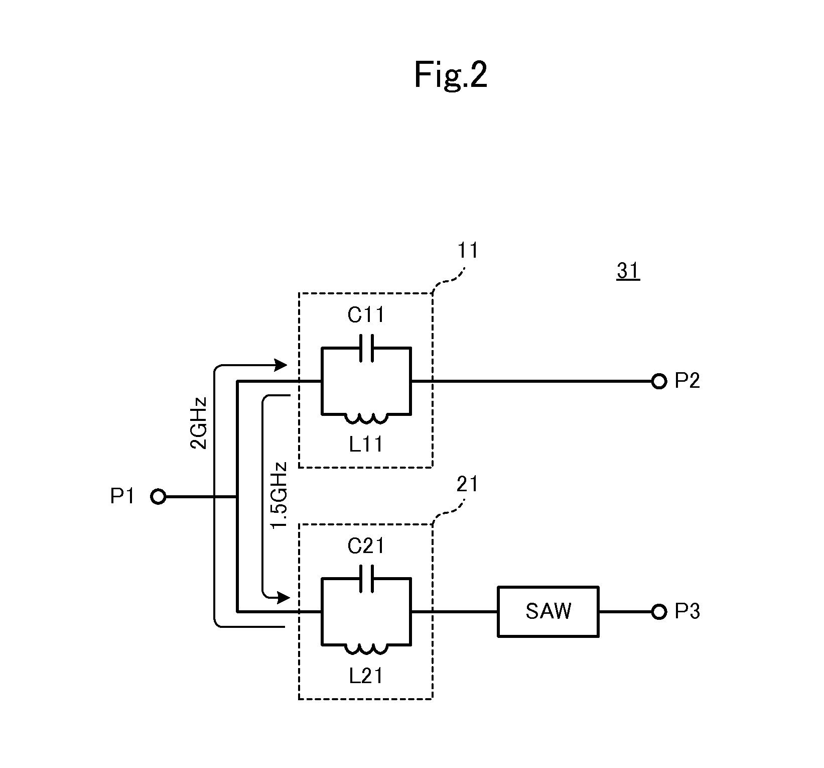
[0060]FIG. 1 is a block diagram of a communication apparatus including a branch circuit according to a first preferred embodiment of the present invention. The communication apparatus includes a branch circuit 31. The branch circuit 31, which includes a common antenna port P1, is a branch circuit that is configured to separate a first communication signal (cellular signal), which includes a signal in a low band and a signal in a high band, and a second communication signal (GPS signal) which is a signal in a frequency band between the low band and the high band. Hereinafter, the “first communication signal” is called a “cellular signal” and the “second communication signal” is called a “GPS signal”.

[0061]In this example, the frequency bands preferably are as follows:

[0062]Low band (800 MHz band: 704 MHz to 960 MHz)

[0063]High band (2.2 GHz band: 1710 MHz to 2690 MHz)

[0064]GPS signal (1.5 GHz band: 1574 MHz to 1606 MHz)

[0065]An antenna 30 is connected to the antenna port P1 of the bra...

second preferred embodiment

[0071]FIG. 4 is a circuit diagram of a branch circuit 32 according to a second preferred embodiment of the present invention. The branch circuit 32 includes an antenna port P1, a cellular signal port P2 and a GPS signal port P3. The branch circuit 32 separates a first communication signal (cellular signal), which includes a signal in a low band and a signal in a high band, and a second communication signal (GPS signal), which is a signal in a frequency band between the low band and the high band.

[0072]Two cellular-signal-line-side band elimination filters 11 and 12 are provided on a cellular signal line. A SAW filter 28, a GPS-signal-line-side band elimination filter 21, and a band pass filter 24 are provided on a GPS signal line. The band pass filter 24 is provided between the GPS-signal-line-side band elimination filter 21 and the SAW filter 28. A capacitor C5 is provided between the band pass filter 24 and the SAW filter 28. A low-noise amplifier (LNA) 29 is provided in a stage s...

third preferred embodiment

[0080]FIG. 8 is a block diagram of a communication apparatus including a branch circuit 33 according to a third preferred embodiment of the present invention. The branch circuit 33 includes an antenna port P1, a cellular signal port P2, and a GPS signal port P3. The branch circuit 33 separates a first communication signal (cellular signal), which includes a signal in a low band and a signal in a high band, and a second communication signal (GPS signal), which is a signal in a frequency band between the low band and the high band.

[0081]An antenna 30 is connected to the antenna port P1 of the branch circuit 33. A communication circuit 10 for cellular signals is connected to the cellular signal port P2 of the branch circuit 33, and a GPS receiver circuit 20 is connected to the GPS signal port P3 of the branch circuit 33.

[0082]Unlike the branch circuit 31 illustrated in FIG. 1, two GPS-signal-line-side band elimination filters 21 and 22 are provided on a GPS signal line. Further, an LNA...


PUM


Abstract

A branch circuit includes a common antenna port and separates a first communication signal including a signal in a low band and a signal in a high band and a second communication signal that is a signal in a frequency band between the low band and the high band. The branch circuit includes a first-communication-signal-line-side band elimination filter and a second-communication-signal-line-side band elimination filter and SAW filter.

Description

BACKGROUND OF THE INVENTION[0001]1. Field of the Invention[0002]The present invention relates to a branch circuit configured to separate communication signals in a plurality of frequency bands and to a branch cable including the branch circuit.[0003]2. Description of the Related Art[0004]In recent years, mobile communication terminal apparatuses, such as cellular phone terminals, need to have a communication function of utilizing many frequency bands, and at the same time, a reduction in the size of the apparatuses is required. Hence, it is difficult to provide many antenna devices for respective frequency bands, and it becomes important to share an antenna and provide a branch circuit for branching antenna signals to a plurality of communication circuits.[0005]Japanese Unexamined Patent Application Publication No. 2005-184773 discloses a branch circuit for switching among three transmission / reception systems: Cellular, GPS, and PCS. FIG. 25 is a circuit diagram of a branch circuit ...

Claims


Application Information

Patent Timeline
Patent Type & Authority Applications(United States)
IPC IPC(8): H04B1/16H04B1/12
CPCH04B1/12H04B1/16H03H7/463H04B1/525H04B1/126H04W84/042
Inventor YOSUI, KUNIAKIKATO, NOBORU
Owner MURATA MFG CO LTD
Why Eureka
Try Eureka