Liquid ejecting apparatus

a technology of liquid ejector and nozzle, which is applied in the direction of printing, etc., can solve the problems of mist (minute ink droplets) being generated due to mist, the operation defects of the printer will be generated, and the ejecting properties of ink droplets that are ejected from the nozzle will deviate from the properties that are originally expected

Active Publication Date: 2016-10-18
SEIKO EPSON CORP
View PDF11 Cites 1 Cited by
  • Summary
  • Abstract
  • Description
  • Claims
  • Application Information

AI Technical Summary

Benefits of technology

[0013]An advantage of some aspects of the invention is to provide a liquid ejecting head that is capable of suppressing the generation of mist, a driving method for the liquid ejecting head, a liquid ejecting apparatus that is provided with the liquid ejecting head, and a driving method for the liquid ejecting apparatus.
[0015]According to the aspect of the present invention, it is possible to match both the initiation potential of the contraction element of the first drive pulse and the initiation potential of the contraction element of the second drive pulse with an intended drive voltage in the piezoelectric properties of the piezoelectric body. As a result of this, it is possible to configure driving of the piezoelectric body by both drive pulses as optimal driving that matches the piezoelectric properties of the piezoelectric body. That is, since the initiation potentials of the contraction elements that cause liquid to be ejected in both drive pulses are also made to be uniform in cases in which the standard potential is increased or decreased in order to adjust one drive pulse to an intended driving range in the piezoelectric properties, it is possible to suppress a circumstance in which the other of the drive pulses deviates from a range of an intended drive voltage in the piezoelectric properties. As a result of this, it is possible to configure driving of the piezoelectric body using both drive pulses and the vibration control element in particular to a target extent. In addition, since the initiation potentials of the contraction elements of both drive pulses are made to be uniform, it is possible to use an effective drive voltage range in the piezoelectric properties of the piezoelectric body sufficiently in both drive pulses, and it is possible to suppress a circumstance in which the vibration control element deviates greatly on a high voltage side. As a result of this, it is possible to suppress a circumstance in which the driving range of the piezoelectric properties of the vibration control element varies for each piezoelectric body, and it is possible to stabilize pressure fluctuations of the pressure chambers due to the vibration control element. In addition to this, in the first drive pulse and the second drive pulse, a difference in potential between the standard potential and the contraction potential is set to 40% or more and 50% or less with respect to a difference in potential between the initiation potential of the contraction element and the contraction potential, and therefore it is possible to suppress the generation of mist and it is also possible to stabilize the ejection of the liquid droplets.
[0017]According to this configuration, since liquid droplets of different sizes are ejected by each drive pulse, multi-gradation recording is possible. In addition, in this case, it is likely that a range of changes in potential (a range from the highest potential to the lowest potential) will differ for each drive pulse, but it is also possible to suppress variation in the driving range in the piezoelectric properties of the vibration control element in such a case, and it is possible to stabilize pressure fluctuations of the pressure chambers due to the vibration control element. In addition to this, regarding each drive pulse, a difference in potential between the standard potential and the contraction potential is set to 40% or more and 50% or less with respect to a difference in potential between the initiation potential of the contraction element and the contraction potential, and therefore, it is possible to more reliably suppress the generation of mist.
[0022]According to this configuration, it is possible to more reliably suppress the generation of mist, and it is possible to stabilize the ejection of the liquid droplets.

Problems solved by technology

When the piezoelectric properties of the piezoelectric body layer deviate, there is a concern that the ejecting properties of ink droplets that are ejected from the nozzles will deviate from the properties that are originally expected.
In this case, in the manner mentioned above, since the vibration control element is an element for controlling vibration of a meniscus after the ejection of the ink droplets, there is a concern that mist (minute ink droplets) will be generated due to the application of the vibration control element.
As a result of this, there is a concern that operational defects of the printer will be generated.
However, as mentioned above, since the intensity of the vibration control due to the vibration control elements varies due to variation in the properties of the piezoelectric element, it is not possible to sufficiently suppress the generation of mist.

Method used


Image

  • Liquid ejecting apparatus
  • Liquid ejecting apparatus
  • Liquid ejecting apparatus

Examples


Embodiment Construction

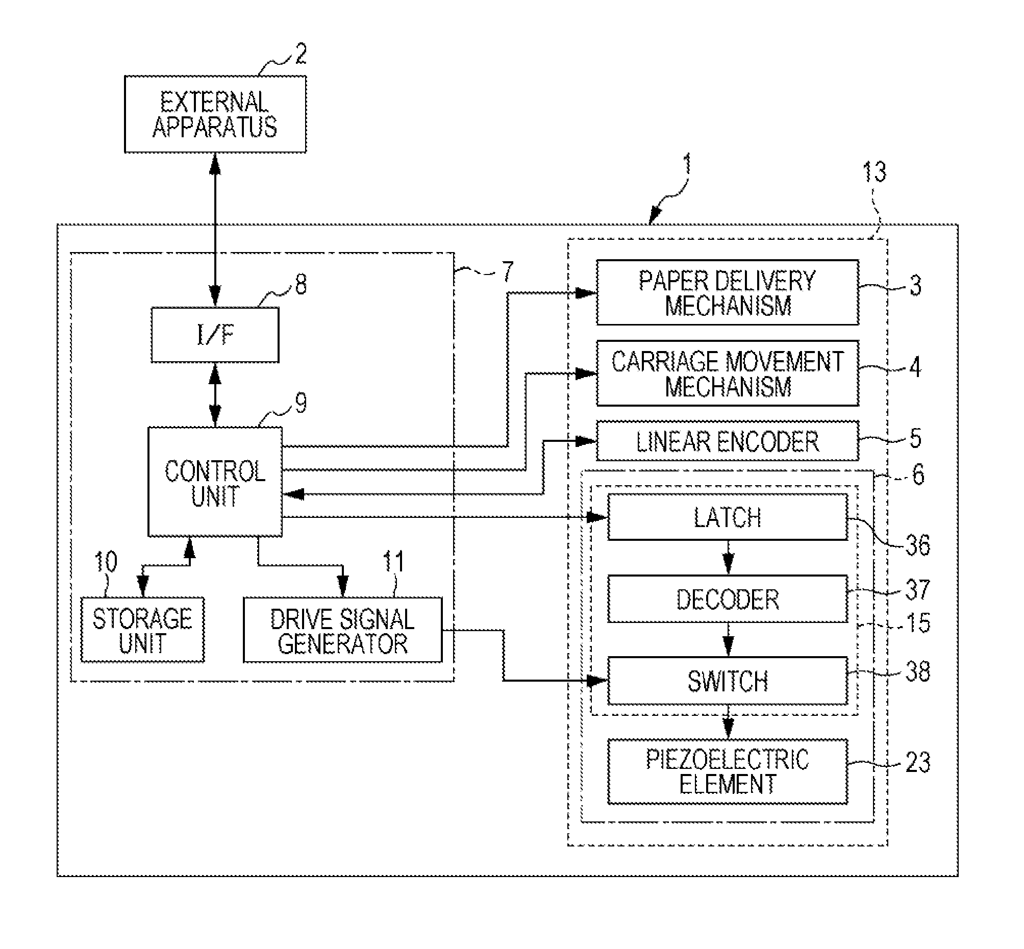
[0034]Hereinafter, an embodiment for implementing the present invention will be described with reference to the appended drawings. Additionally, in the embodiments that will be described below, various limitations are given as preferred specific examples of the present invention, but the scope of the present invention is not limited to these aspects unless a feature that limits the present invention is specifically stated in the following description. In addition, in the following description, an ink jet type recording apparatus (hereinafter, referred to as a printer 1) is used as an example of a liquid ejecting apparatus of the present invention.

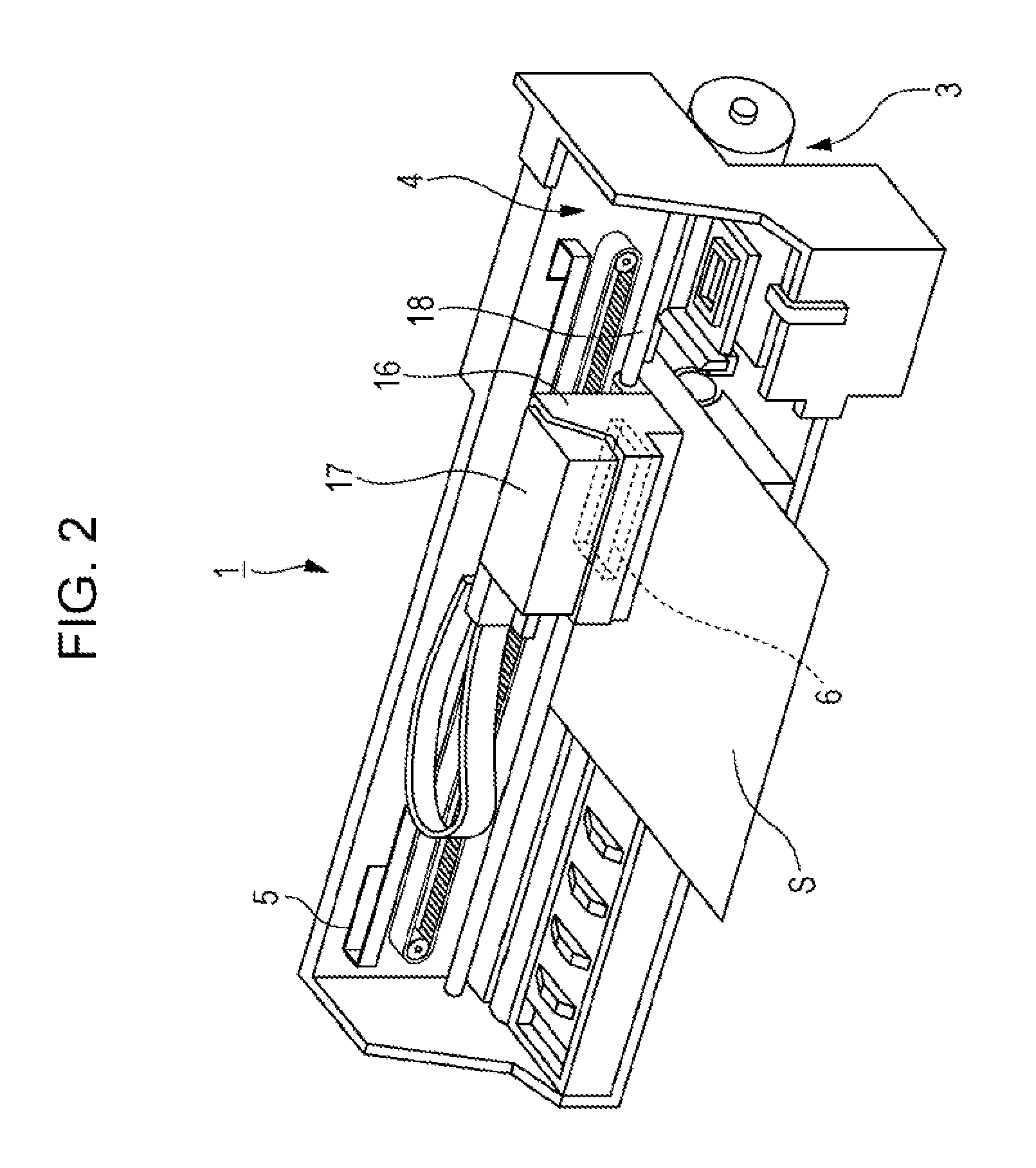
[0035]FIG. 1 is a block diagram that describes an electrical configuration of a printer 1 and FIG. 2 is a perspective view that describes an internal configuration of the printer 1. An external apparatus 2 is for example, an electronic device such as a computer, a digital camera, a cellular phone, or a mobile data terminal device. The exter...


PUM


Abstract

A drive signal includes a first drive pulse that causes liquid droplets to be ejected from nozzles and a second drive pulse that causes liquid droplets of a different size from those of the first drive pulse to be ejected from the nozzles. The drive pulses have expansion elements that expand a pressure chamber, contraction elements that contract a pressure chamber, and vibration control elements. An initiation potential of the contraction element of the first drive pulse and an initiation potential of the contraction element of the second drive pulse are the same. The differential voltage between the standard potential and the contraction potential is set to between 40% 50% or less of the potential between the initiation potential of the contraction element and the contraction potential.

Description

BACKGROUND[0001]1. Technical Field[0002]The present invention relates to a liquid ejecting head that causes liquid droplets to be ejected from nozzles by supplying a drive signal to a piezoelectric body. The present invention also relates to a driving method for the liquid ejecting head, a liquid ejecting apparatus that is provided with the liquid ejecting head, and a driving method for the liquid ejecting apparatus.[0003]2. Related Art[0004]A liquid ejecting apparatus is an apparatus that is provided with a liquid ejecting head that is capable of ejecting a liquid in the form of liquid droplets from nozzles, and which liquid ejecting apparatus ejects various kinds of liquids from the liquid ejecting head. For example, as representative examples of this kind of liquid ejecting apparatus, there are image recording apparatuses (hereinafter, referred to as printers) such as ink jet recording apparatuses that are provided with an ink jet recording head (hereinafter, referred to as a rec...

Claims


Application Information

Patent Timeline
Patent Type & Authority Patents(United States)
IPC IPC(8): B41J2/045
CPCB41J2/04588B41J2/04581B41J2/04593
Inventor FUKUDA, SHUNYA
Owner SEIKO EPSON CORP
Why Eureka
Try Eureka