
Arc atmospheric pressure plasma device

a plasma device and atmospheric pressure technology, applied in plasma techniques, electrical equipment, electric discharge tubes, etc., can solve the problems of limited treatment range non-uniform plasma treatment, limited application of arc atmospheric pressure plasma, etc., to achieve the effect of improving the uniformity of treatment and increasing the treatment area of plasma scanning operation

Active Publication Date: 2016-10-18
CREATING NANO TECH INC
View PDF6 Cites 2 Cited by
  • Summary
  • Abstract
  • Description
  • Claims
  • Application Information

AI Technical Summary

Benefits of technology

The present invention provides an arc atmospheric pressure plasma device with a plasma nozzle having at least two nozzle channels, which increases the amount of plasma ejected and makes the plasma treatment path denser. This increases the treatment area and improves uniformity compared to a device with one single nozzle channel. The nozzle with a multi-channel design blocks the arc and only plasma is ejected, which prevents damage to the treated surface due to a direct hit of the arc, improving the quality of the plasma treatment.

Problems solved by technology

However, because an arc of the arc atmospheric pressure plasma has a negative resistance property, an arc discharge with a large area cannot be generated, thus a treating range of the arc atmospheric pressure plasma is limited, and an application of the arc atmospheric pressure plasma is limited.
However, in this technique, there are many disadvantages resulted from rotating the nozzle which is one of the electrodes.
Thus, a plasma treatment is non-uniform, and reliability and quality of the treatment are poor.

Method used


Image

  • Arc atmospheric pressure plasma device
  • Arc atmospheric pressure plasma device
  • Arc atmospheric pressure plasma device

Examples


Embodiment Construction

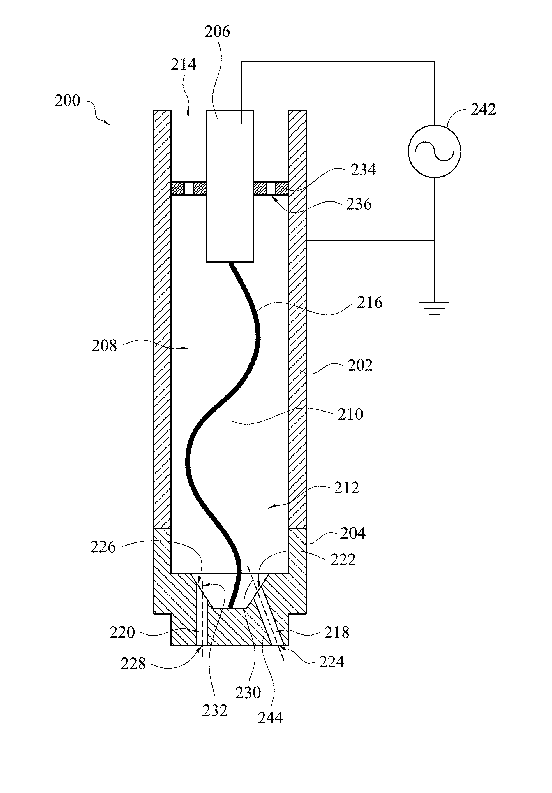
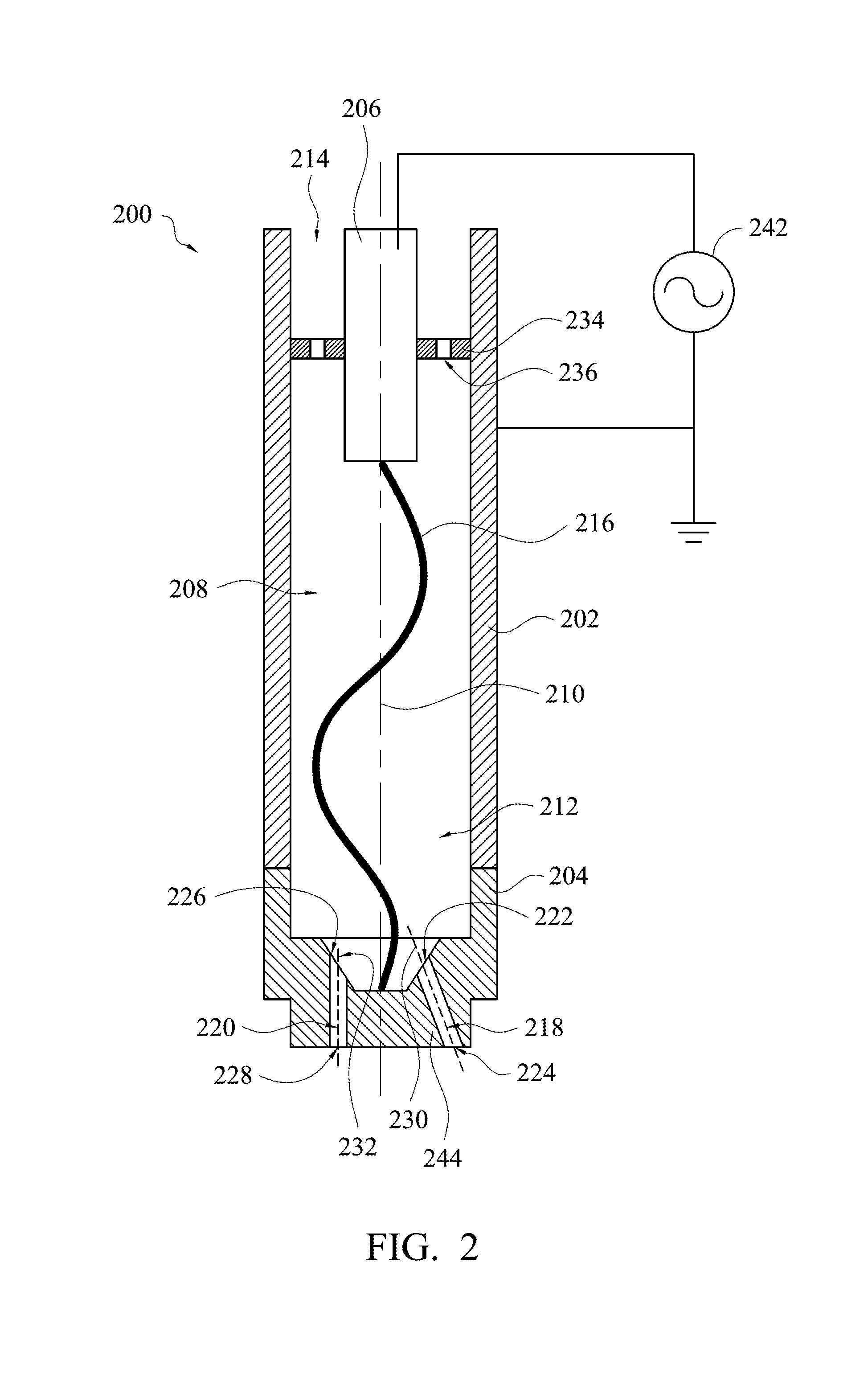
[0028]Referring to FIG. 2, FIG. 2 is schematic drawing of an arc atmospheric pressure plasma device in accordance with one embodiment of the present invention. In some examples, an arc atmospheric pressure plasma device 200 mainly includes a first electrode 206, a nozzle 204 and a second electrode 202. The first electrode 206 is configured to connect to a power supply 242. The first electrode 206 may be, for example, a rod electrode, as shown in FIG. 2. The first electrode 206 may be a hollow electrode. In some examples, the power supply 242 is a high frequency and high voltage power supply. In some exemplary examples, an output frequency of the power supply 242 ranges from 1 kHz to 60 kHz, and a voltage of the power supply 242 ranges from 5 kV to 20 kV.

[0029]The second electrode 202 may be a tubular electrode and have a chamber 208. The second electrode 202 is grounded. In addition, the second electrode 202 has openings 212 and 214, which are respectively disposed at two opposite e...


PUM


Abstract

An arc atmospheric pressure plasma device is described. The arc atmospheric pressure plasma device includes a first electrode, a second electrode and a nozzle. The first electrode is configured to connect to a power supply. The second electrode has a chamber and is grounded. The first electrode is located within the chamber. The nozzle is connected to a bottom of the second electrode, and has at least two nozzle channels. The nozzle channels communicate with the chamber.

Description

RELATED APPLICATIONS[0001]This application claims priority to Taiwan Application Serial Number 104127701, filed Aug. 25, 2015, which is herein incorporated by reference.BACKGROUND[0002]1. Field of Invention[0003]The present invention relates to a plasma device. More particularly, the present invention relates to an arc atmospheric pressure plasma device.[0004]2. Description of Related Art[0005]Currently, atmospheric pressure plasma has been widely applied on surface treatments in various fields, so as to increase reliability of processes, such as adhesion, printing, package and bonding processes. However, because an arc of the arc atmospheric pressure plasma has a negative resistance property, an arc discharge with a large area cannot be generated, thus a treating range of the arc atmospheric pressure plasma is limited, and an application of the arc atmospheric pressure plasma is limited.[0006]Although the arc atmospheric pressure plasma cannot generate arc discharge with a large ar...

Claims


Application Information

Patent Timeline
Patent Type & Authority Patents(United States)
IPC IPC(8): H05H1/40H05H1/34H05H1/48H05H1/36H05H1/24
CPCH05H1/34H05H1/48H05H1/36H05H1/24H01J37/3244H01J37/32532H05H1/32H05H1/3463
Inventor HONG, CHAU-NANHSU, YI-MINGWANG, LI-MIN
Owner CREATING NANO TECH INC
Learn More