Foot operated propulsion system for watercraft

a propulsion system and watercraft technology, applied in the field of watercraft, can solve problems such as not allowing the operator to stand up

Active Publication Date: 2016-10-25
HOBIE CAT IP LLC
View PDF122 Cites 34 Cited by
  • Summary
  • Abstract
  • Description
  • Claims
  • Application Information

AI Technical Summary

Problems solved by technology

However, this does not permit the opportunity for the operator to stand up or rest on an elevated seat located well above the upper extremity of the hull.

Method used


Image

  • Foot operated propulsion system for watercraft
  • Foot operated propulsion system for watercraft
  • Foot operated propulsion system for watercraft

Examples


Embodiment Construction

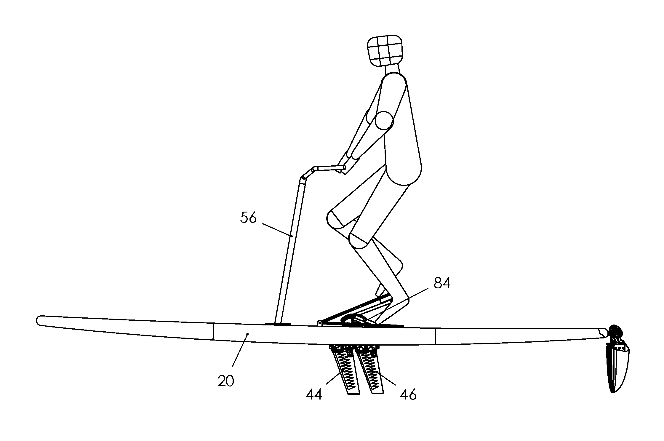
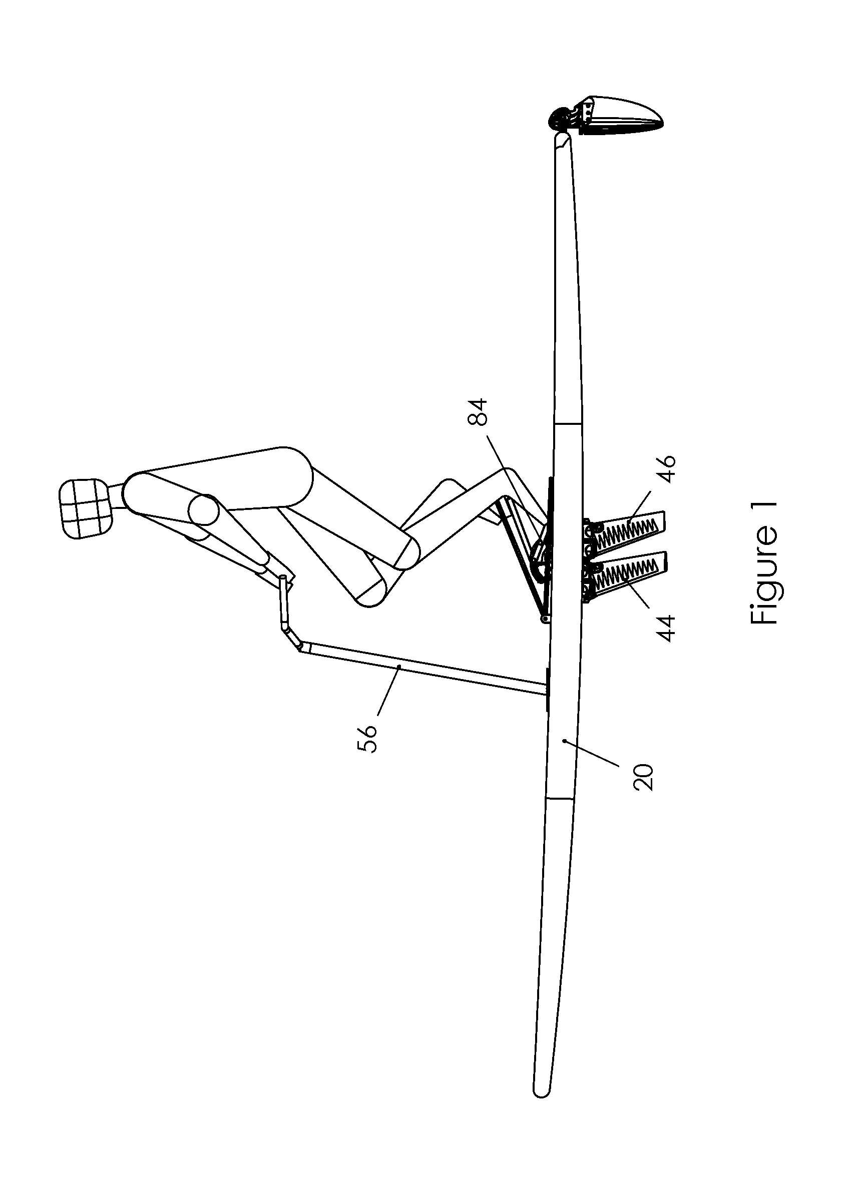
[0032]Turning to the drawings in more detail, the pedals 10 and 12 are in slidable contact with pedal cranks 14 and 16, respectively as further described hereinbelow. The pedal cranks 14 and 16 are operatively connected at member 84 to the propulsion means which is recessed in an opening 18 in the center of the paddle board 20 or kayak 21. The forward end of each of the pedals 10 and 12 are pivotally attached at 22 and 24 to the upper surface 26 of paddle board or kayak.

[0033]The underside 28 at the rear or trailing ends 30, 32 of the pedals 10 and 12 are each adapted to make rolling contact with bearings 34 and 36 attached to the free ends of the cranks 14 and 16, respectively. The underside 28 of the pedals 10 and 12 can also make sliding contact with the free ends of the cranks. The standing operator or user of the paddle board or a seated operator of a boat such as a kayak by applying step-stair movement with the legs to the pedals causes the cranks to move up and down, such tha...


PUM


Abstract

A device for insertion in watercraft including propulsion means comprising a pair of flappers which oscillate through an arcuate path in a transverse direction with respect to the central longitudinal dimension of the watercraft. As input force is applied, the flappers twist to form an angle of attack for providing forward thrust. The means for applying propulsive force includes a pair of pedals, and further includes pedal cranks operatively associated with the propulsion means, the fore ends of the pedals being pivotally attached to a fixed point.

Description

FIELD OF INVENTION[0001]This invention relates to novel watercraft.BACKGROUND OF INVENTION[0002]There exists a wide array of recreational watercraft including paddle boards and boats such as kayaks. In one prior kayak, propulsion is provided while the operator is seated within a cockpit in the kayak with pedals positioned fore. However, this does not permit the opportunity for the operator to stand up or rest on an elevated seat located well above the upper extremity of the hull.[0003]The present invention affords an entirely new sensation for the operator of a kayak, paddle board or other watercraft.SUMMARY OF THE INVENTION[0004]Briefly, this invention comprises a device adapted to be inserted in a watercraft comprising propulsion means extending below the water line carried by a support member, said propulsion means comprising a pair of flexible flappers each adapted to oscillate through an arcuate path in a generally transverse direction with respect to the central longitudinal d...

Claims


Application Information

Patent Timeline
Patent Type & Authority Patents(United States)
IPC IPC(8): B63H1/36B63H16/18B63B35/71B63B35/79B63H16/08
CPCB63H1/36B63B35/71B63B35/79B63H16/12B63H16/18B63H1/37B63H16/20B63H2016/202B63B32/40B63B32/64
Inventor CZARNOWSKI, JAMES TAYLORKETTERMAN, GREGORY SCOTTKARDAS, JASON CHRISTOPHERDOW, PHILIP JAMESWICKS, GRAEME STUARTBRACKETT, DREW WILLIAM
Owner HOBIE CAT IP LLC
Why Eureka
Try Eureka