High current slipring for multi fiber brushes

a multi-fiber brush and slipring technology, applied in current collectors, rotary current collectors, electrical appliances, etc., can solve the problems of limiting the movement of brush wires and additional contact noise, and achieve the effects of reducing contact resistance and contact noise, improving current capacity, and improving current capacity

Active Publication Date: 2016-11-08
SCHLEIFRING & APPBAU
View PDF16 Cites 2 Cited by
  • Summary
  • Abstract
  • Description
  • Claims
  • Application Information

AI Technical Summary

Benefits of technology

[0006]The embodiments are based on the object of providing a slip ring further providing an improved capacity, further reduced contact resistance and contact noise, and further increased current capacity. A further object is to provide a sliding track having improved capacity, further reduced contact resistance and contact noise, and further increased current capacity.
[0012]Due to the convex sliding track, there is a better distribution of the brush wires on the sliding track. Tests have shown that more than 90% of the brush wires are in immediate contact with the sliding track. Therefore, by using a sliding track according to the previous embodiments, the number of brush wires staying in sliding contact with the sliding track can be increased without increasing the total number of sliding wires. This leads to an increased current capacity, lower contact resistance and lower contact noise. Furthermore, heat is dissipated over a larger surface and better distributed over the wires and the track surface, which further increases current capacity and lifetime by decreasing wear. Due to the increased current capacity, sliprings may be built smaller. Especially, if there is a high number of sliding wires in an embodiment as known from prior art having a concave sliding track, the wires may shift their location relative to the other wires. This causes additional contact noise. Such a contact noise is prevented by the embodiments described herein.

Problems solved by technology

These grooves may limit the movement of brush wires.
This causes additional contact noise.

Method used


Image

  • High current slipring for multi fiber brushes
  • High current slipring for multi fiber brushes
  • High current slipring for multi fiber brushes

Examples


first embodiment

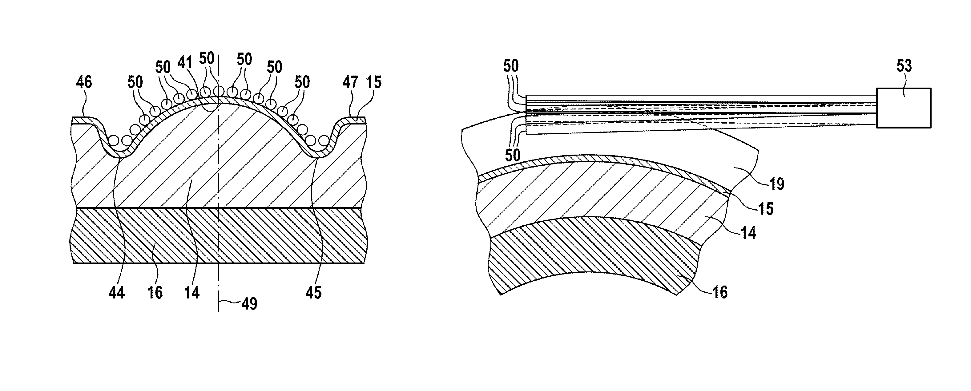
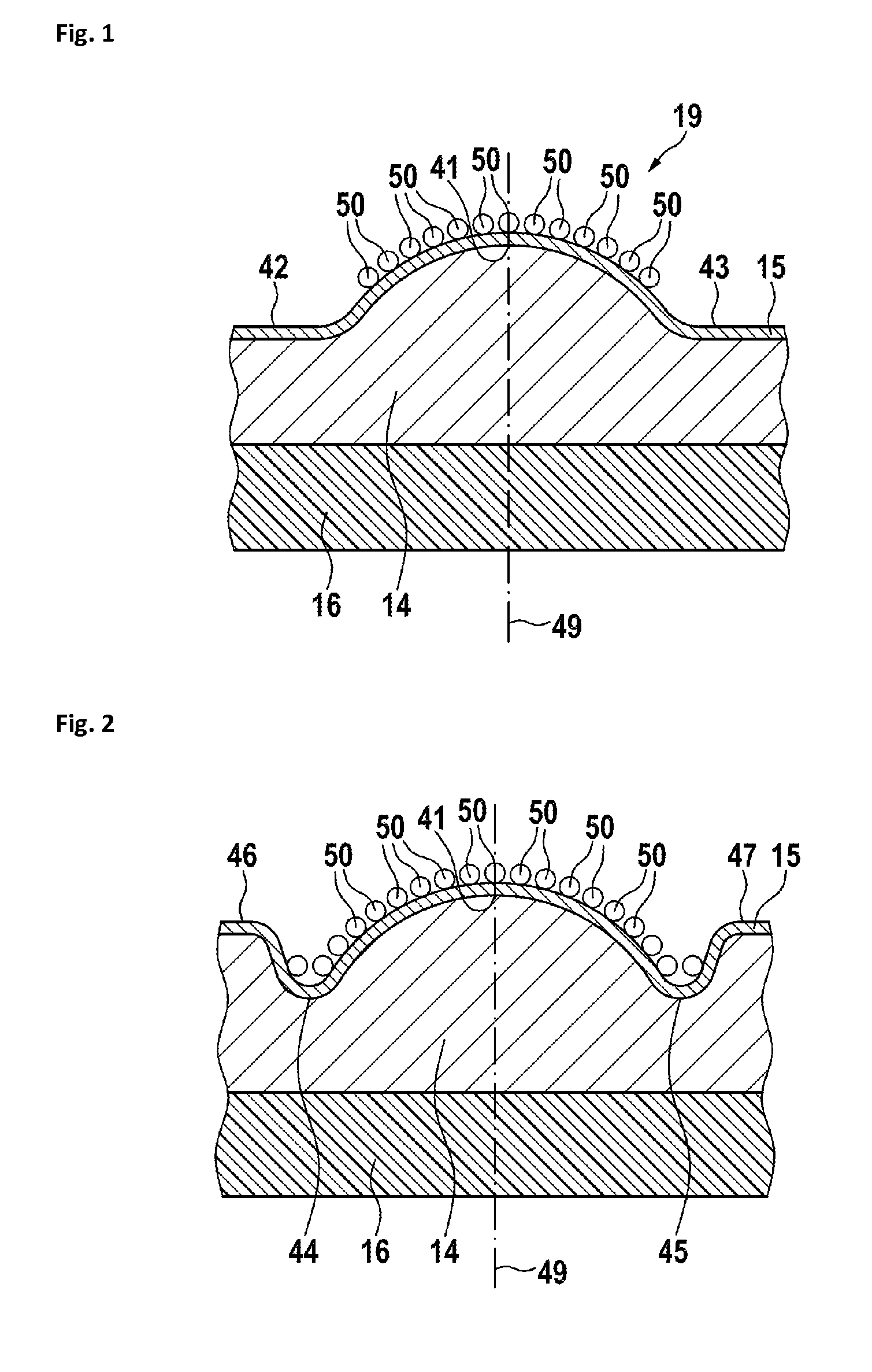
[0023]In FIG. 1, a sectional view of a convex sliding track is shown. The sliding track has a sliding track body 14. The sliding track body 14 is held by or embedded into slip ring body 16. To allow a good electric contact with the brushes, there is a sliding track coating 15 at the surface of sliding track body 14. A plurality of brush wires 50 are sliding at the sliding track coating. The sliding track basically has a convex shaped cross-section 19 with a center section 41 defining the center plane 49. Besides this center section, preferably there are side wings 42 and 43, which preferably are also coated as previously described. During normal operation, the wires 50 are sliding on the convex-shaped sliding track portion and do not slide on the side wings. These may provide some safety margin for the case the wires 50 leave their normal position. This may be caused by misalignment, shock, or vibration. The convex sliding track may have a cross-section of a segment of a sphere, an...

second embodiment

[0024]In FIG. 2, a sectional view of a sliding track is shown. Here, side grooves 44 and 45 are configured to catch any brush wires sliding away from the convex-shaped sliding track. Furthermore, elevated sides 46 and 47 may be configured to provide an additional safety margin.

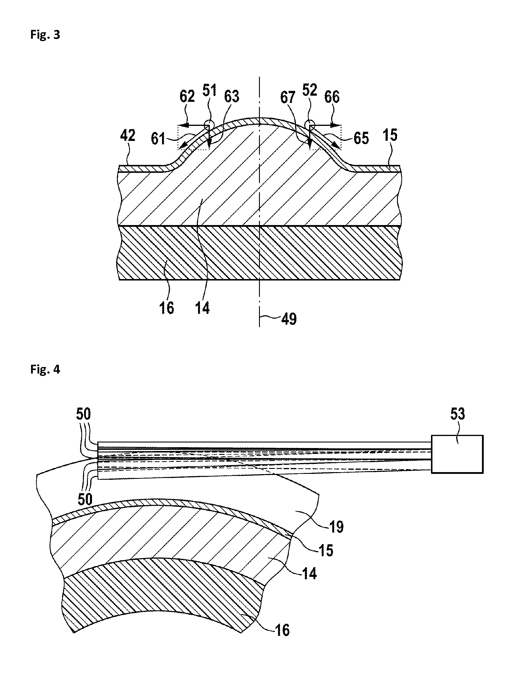
[0025]In FIG. 3, forces at sliding wires are shown in a sectional view of a sliding track. In this example, only two sliding wires are shown for simplicity. Basically, the same forces apply, if there is a larger number of sliding wires. A first brush wire 51 is shown at the left side of center plane 49, while a second brush wire 52 is shown at the right side of the center plane 49. The forces, which apply to the brushes 51 and 52, are symmetrical to the center plane 49. At the first brush 51, a first tangential force 61 pulls the brush outwards to the left side. This force has two components. A first component 62 pulls the brush at a right angle to the center plane away from the center plane, while a second fo...


PUM


Abstract

A slipring comprises a slipring module rotating about a rotation axis, having a plurality of sliding tracks and at least one multi wire brush sliding thereon. The sliding tracks have a circular contact surface with its center located at the rotation axis and a convex shaped cross-section. Due to this convex shaped sliding track, the individual brush wires of the multi wire brush distribute over the sliding track surface and offer a higher number of contact points. This results in a higher current capacity, lower contact resistance and lower contact noise.

Description

CROSS-REFERENCE TO RELATED APPLICATIONS[0001]This application is a continuation of pending International Application No. PCT / EP2013 / 060268 filed on 17 May 2013, which designates the United States. The entire disclosure of the International Application is incorporated by reference herein.FIELD OF THE INVENTION[0002]The invention relates to slip rings for the transmission of electrical signals and / or energy by means of sliding contacts between rotatable parts. In such a sliding contact, a brush is slidable on a sliding track, also called slipring track. The brush and the sliding track comprise electrically conductive materials. The contact between the brush and the sliding track establishes a galvanic connection by which the electric current may be transferred.DESCRIPTION OF RELEVANT ART[0003]A slip ring is disclosed in DE 14 89 080 A. Here, the brushes comprise solid single wires running in grooves of a track.[0004]Another slip ring is disclosed in EP 0 662 736 A, having multi-wire b...

Claims


Application Information

Patent Timeline
Patent Type & Authority Patents(United States)
IPC IPC(8): H01R39/64H01R39/08H01R39/24
CPCH01R39/64H01R39/08H01R39/24
Inventor HOLZAPFEL, CHRISTIAN
Owner SCHLEIFRING & APPBAU
Why Eureka
Try Eureka