Reconfigurable compensator with large-signal stabilizing network

a compensator and large-signal technology, applied in the direction of battery data exchange, charging and exchanging data, transportation and packaging, etc., can solve the problems of affecting the user experience, increasing the size and cost of the device, and frustrating users

Active Publication Date: 2016-11-08
APPLE INC
View PDF16 Cites 5 Cited by
  • Summary
  • Abstract
  • Description
  • Claims
  • Application Information

AI Technical Summary

Benefits of technology

[0012]Another embodiment provides a method for reducing transients associated with a transition from a first error signal to a second error signal. During the method, a transition is made from the first error signal to the second error signal for use in charging the battery, where the first error signal and the second error signal, respectively, correspond to feedback sources in the plurality of feedback sources. Then, the gain and the impedance to ground of the damping circuit are selected based on the selected second error signal, where the damping circuit applies the gain and the impedance to ground to the second error signal. Next, the one or more clamping voltages of the voltage-clamping circuit are selected based on the selected second error signal, where the voltage-clamping circuit applies the one or more clamping voltages to an output from the damping circuit.

Problems solved by technology

These variations often require more complexity in the charger circuit (with a commensurate increase in size and cost) or require the use of a particular power adapter with a given portable electronic device, which can be frustrating to users and can degrade the user experience.

Method used


Image

  • Reconfigurable compensator with large-signal stabilizing network
  • Reconfigurable compensator with large-signal stabilizing network
  • Reconfigurable compensator with large-signal stabilizing network

Examples


Embodiment Construction

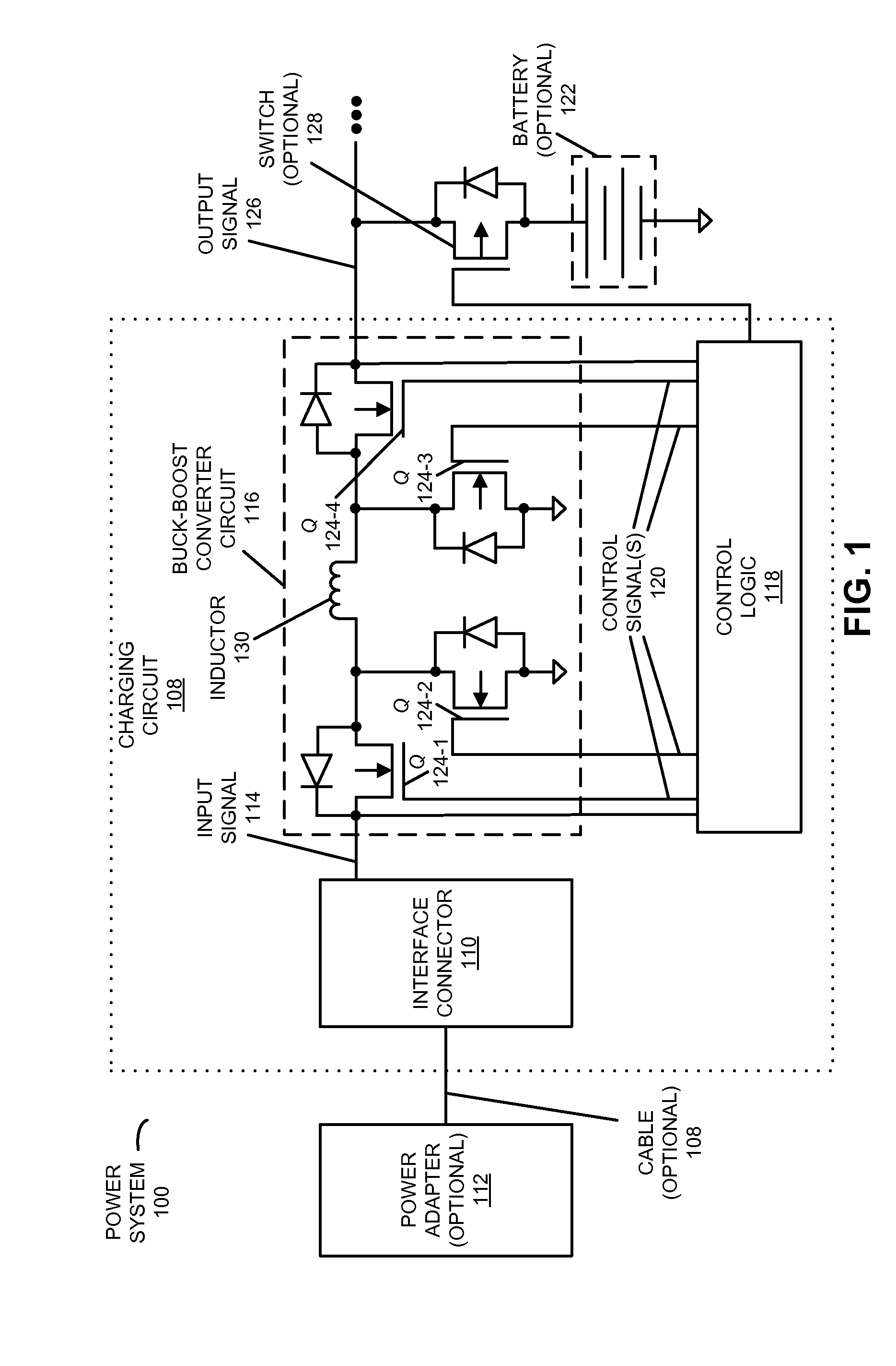
[0023]FIG. 1 presents a block diagram illustrating a power system 100 that includes: optional power adapter 112, a charger circuit 108, switch 124, optional switch 128 and optional battery 122. Moreover, charger circuit 108 may include: an interface connector 110, a buck-boost converter circuit 116 and control logic 118. Furthermore, buck-boost converter circuit 116 may include: switches 124 and inductor 130. The switches may comprise a first switch 124-1 that may selectively couple a first side of inductor 130 to interface connector 110, a second switch 124-2 that may selectively couple the first side of inductor 130 to ground, a third switch 124-3 that may selectively couple a second side of inductor 130 to ground, and a fourth switch 124-4 that may selectively provide output signal 126 to optional battery 122 and / or a system load. For example, fourth switch 124-4 may selectively couple the second side of inductor 130 to optional battery 122 (although it should be appreciated that...


PUM


Abstract

During operation, the DC converter and a DC battery charger controller in a charger circuit transitions from a first error signal to a second error signal for use in charging a battery, wherein the first error signal and the second error signal, respectively, correspond to feedback sources in a plurality of feedback sources with a plurality of feedback sources. Then, the DC converter and a DC battery charger controller selects a gain and an impedance to ground of a damping circuit based on the selected second error signal, where the damping circuit applies the gain and the impedance to ground to the second error signal. Moreover, the DC converter and a DC battery charger controller selects one or more clamping voltages of a voltage-clamping circuit based on the selected second error signal, where the voltage-clamping circuit applies the one or more clamping voltages to an output from the damping circuit.

Description

CROSS-REFERENCE TO RELATED APPLICATION[0001]This application claims priority under 35 U.S.C. §119(e) to U.S. Provisional Application Ser. No. 61 / 875,551, entitled “Universal Power Adapter,” by Yongxuan Hu, Arthur H. Chang, Shimon Elkayan, Collin Conners and Liyu Yang, filed on Sep. 9, 2013, the contents of which are herein incorporated by reference.BACKGROUND[0002]1. Field[0003]The described embodiments relate to techniques for controlling operation a charger circuit associated with a battery. More specifically, the described embodiments relate to techniques for selecting a feedback source, gain and impedance to ground, and / or one or more clamping voltages in the charger circuit.[0004]2. Related Art[0005]During charging, a portable electronic device is typically connected to a power adapter, which transforms an AC power-line voltage into a DC input voltage that is used to charge the battery and / or power the portable electronic device. Moreover, many portable electronic devices inclu...

Claims


Application Information

Patent Timeline
Patent Type & Authority Patents(United States)
IPC IPC(8): H02J7/00
CPCH02J7/0052H02J7/007H02J7/0065H02J7/0004H02J2007/0059H02M3/1582H02J2207/20H02J7/00036H02J7/00047H02J7/00
Inventor CHANG, ARTHUR H.HU, YONGXUANELKAYAM, SHIMON
Owner APPLE INC
Why Eureka
Try Eureka