Cleaning of a turbo-machine stage

a technology of turbo-machine and cleaning method, which is applied in the direction of machines/engines, mechanical equipment, manufacturing tools, etc., can solve the problems of inability to optimally act on engine stages, particularly turbine stages located further downstream, and the negative impact of airplane engines

Active Publication Date: 2016-11-15
MTU AERO ENGINES GMBH
View PDF14 Cites 14 Cited by
  • Summary
  • Abstract
  • Description
  • Claims
  • Application Information

AI Technical Summary

Benefits of technology

[0010]It is advantageous that due to sublimation less or no liquid wastes have to be discarded. On the other hand, the sudden sublimation as well as the thermal shock can be used advantageously in addition to the kinetic energy in order to clean the blades.
[0012]The solid particles can be applied to the blades in a gas jet, for example, as a dry ice jet, or as a finely distributed solid snow, for example, a CO2 snow. The particles of a dry ice jet, which are obtained from “solid CO2,” typically have a higher density and as a result they produce a stronger mechanical attack against the soiling. On the other hand, CO2 snow (produced from compressed CO2 gas) has a gentler action. Furthermore, additional media (hard particles) can be introduced into the dry ice, in order to increase the cleaning effect.
[0023]In order to shorten the cleaning time, it can be advantageous, as already explained, to introduce several cleaning nozzles and / or act upon several blades and / or stages at the same time. Two cleaning nozzles here can act similarly on different blades of the same stage or blades of different stages. This depends particularly on the cleaning or inspection openings through which the cleaning nozzles are introduced. It can be advantageous for the inspection or cleaning openings or the cleaning nozzles introduced into the latter to be mutually offset in the peripheral direction in different stages, so that a cleaning agent that flows past a blade additionally hits axially adjacent blades which at that time are not acted upon. Similarly, it can be advantageous if the inspection or cleaning openings or the cleaning nozzles introduced into the latter are not mutually offset in the peripheral direction in different stages, so that the access is simplified over the axial length of the turbo-machine. In the case of several cleaning nozzles for one stage, it is possible to provide that each blade is acted upon only by the same nozzle, so that all the blades are already swept over in the case of a rotation by 360° divided by the number of the cleaning nozzles. Similarly, it is possible to provide that each blade is acted upon by different nozzles, so that the cleaning action is increased. For example, if two cleaning nozzles are arranged with mutual offset by the blade separation in the peripheral direction, the stage can be further rotated, on the one hand, by twice the blade separation, so that each nth blade is acted upon by the first, and each (n+1)th blade by the second cleaning nozzle. Similarly, the stage can be further rotated by the blade separation, so that each blade is acted upon by the first and then by the second cleaning nozzle.
[0025]In addition or alternatively, at least one radially front portion of the cleaning nozzle can be produced from a material, particularly aluminum or an aluminum alloy, which is softer than the turbo-machine stage, in order to minimize in this manner damage to the stage during an unwanted contact with the cleaning nozzle. In particular, a material in the sense of the present invention is softer than another material, if its Brinell, Vickers or Rockwell hardness or the hardness determined according to another method is at least 10% lower than that of the other material.
[0029]According to a preferred embodiment of the present invention, the cleaning nozzle has one or more handles for thermal insulation, to protect the user from the cold of the dry ice.

Problems solved by technology

Impurities, for example, sand, dust, volcanic ash, sea or fertilizer salt, chemicals, oil, lubricants and the like are deposited on the blades of the individual compressor and turbine stages of airplane engine gas turbines, and adhere there, becoming encrusted in particular, so that the airplane engine is negatively affected.
The disadvantage here is, on one hand, that the soiled cleaning agent has to be discarded after use by means of a separate collection device, and, on the other hand, the engine stages, particularly turbine stages, located further downstream cannot be acted on optimally.

Method used


Image

  • Cleaning of a turbo-machine stage
  • Cleaning of a turbo-machine stage

Examples


Embodiment Construction

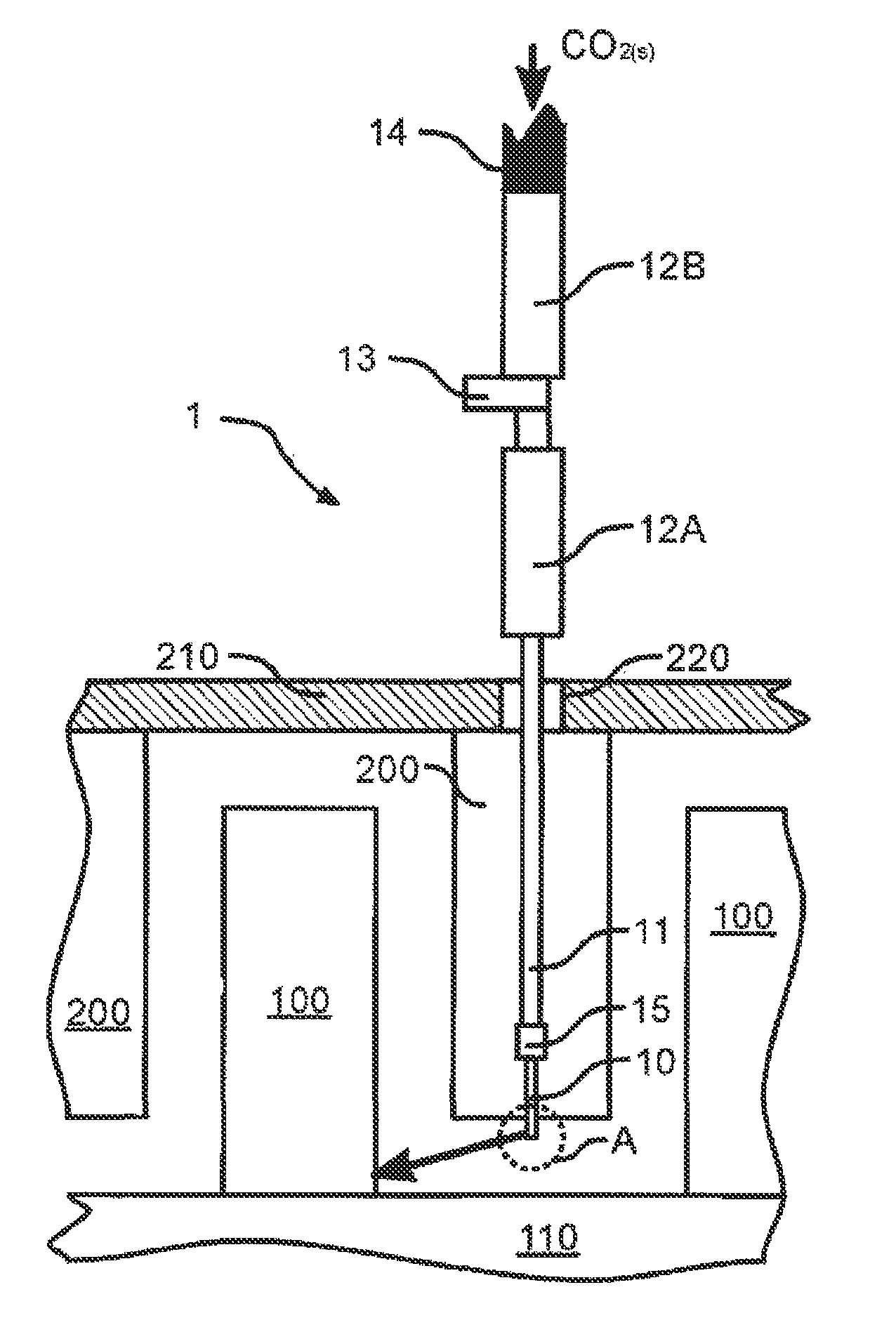
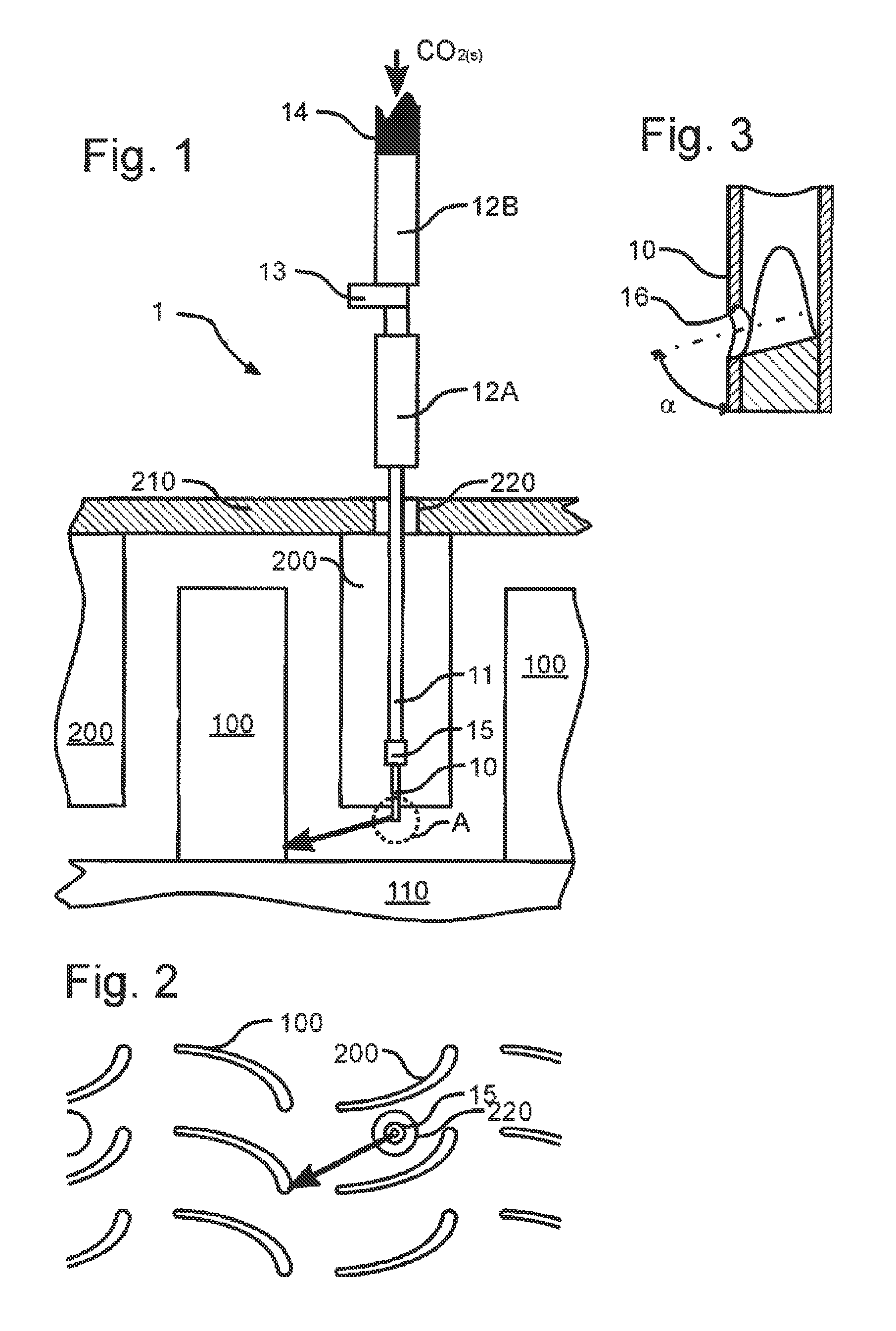
[0034]FIG. 1 shows a portion of a high-pressure compressor or a high-pressure turbine of an airplane engine in an axial cross section with several stages each comprising rotor blades 100 and stator blades 200.

[0035]Between two stator blades of a stage, as one can see particularly in FIG. 2, an inspection opening 220 is provided in the flow channel and engine outer wall 210, which can be closed in a detachable manner by a plug (not shown, because removed in FIGS. 1, 2).

[0036]Through this opening 220, a cleaning nozzle 1 is introduced. It comprises a guide pipe 11 made of a steel or aluminum alloy with two thermally insulating handles 12A, 12B and a detachable clamp 13, as well as an inner pipe 10 which can be displaced in the guide pipe 11, and on the front face of which, facing away from the handles, nozzle opening 16 is arranged, which is represented in detail in FIG. 3. This clamp 13 can be designed as a rubber fixation and / or as a magnet. Furthermore, the inner pipe 10 can be mad...


PUM

PropertyMeasurementUnit
pressureaaaaaaaaaa
angleaaaaaaaaaa
temperatureaaaaaaaaaa

Abstract

The invention relates to a method for cleaning a turbo-machine stage (100) consisting of at least one of the following steps: a cleaning nozzle (1) is introduced into an opening of a turbo-machine, in particular into an inspection opening (220); and the blade (100) of the stage is acted upon by solid particles, said particles subliming at the blade temperature, in particular into dry ice particles.

Description

CROSS-REFERENCE TO RELATED APPLICATIONS[0001]This application is a U.S. National Phase application submitted under 35 U.S.C. §371 of Patent Cooperation Treaty application serial no. PCT / DE2011 / 001545, filed Aug. 3, 2011, and entitled CLEANING OF A TURBO-MACHINE STAGE, which application claims priority to German patent application serial no. 10 2010 033 157.0, filed Aug. 3, 2010, entitled REINIGUNG EINER TURBOMASCHINENSTUFE and German patent application serial no. 10 2010 045 869.4, filed Sep. 17, 2010, entitled REINIGUNG EINER TURBOMASCHINENSTUFE.[0002]Patent Cooperation Treaty application serial no. PCT / DE2011 / 001545, published as WO 2012 / 025090, German patent application serial no. 10 2010 033 157.0, and German patent application serial no. 10 2010 045 869.4, are incorporated herein by reference.TECHNICAL FIELD[0003]The invention relates to a method for cleaning a machine stage of a gas turbine as well as to the use of a cleaning nozzle in such a method.BACKGROUND[0004]Impurities,...

Claims


Application Information

Patent Timeline
Patent Type & Authority Patents(United States)
IPC IPC(8): B08B7/00F01D25/00B24C1/08B24C3/32B08B9/00B24C1/00
CPCB24C1/003B08B7/0021B08B9/00B24C1/086B24C3/325F01D25/002
Inventor ROSING, JURGENSEIDEL, FRANKWINKLER, LUTZKRIEGL, BERNDUIHLEIN, THOMASDURR, MARTINMORITZ, FABIAN
Owner MTU AERO ENGINES GMBH
Why Eureka
Try Eureka