
Aircraft wheel bearing arrangement

a technology for aircraft wheels and bearings, applied in the direction of wheel bearings, hubs, transportation and packaging, etc., can solve the problems of aircraft wheels that are subjected to carbon dust, aircraft wheels that are subjected to not only high energy braking events that can produce significant heat, and may be harsh and demanding, so as to maximize the internal wheel volume, optimize the stiffness and structural integrity of the wheel, and ensure the effect of bearing suppor

Active Publication Date: 2016-11-15
BOREALIS TECH LTD
View PDF22 Cites 1 Cited by
  • Summary
  • Abstract
  • Description
  • Claims
  • Application Information

AI Technical Summary

Benefits of technology

The present invention provides a bearing arrangement for an aircraft landing gear wheel that supports the wheel while maximizing its internal space and stiffness. This arrangement minimizes the number of bearing structures required to effectively support the wheel and also provides structural stiffness and integrity to the wheel while maximizing its internal space. The bearing arrangement also includes a specifically configured cantilevered joint portion that supports weight and loads the bearings, eliminating the need for and space required by a high speed bearing. The invention is useful in aircraft equipped with onboard non-engine drive means controllable to move the aircraft on the ground autonomously without reliance on the aircraft's main engines or external tow vehicles.

Problems solved by technology

The conditions under which aircraft wheels must operate during service, moreover, may be harsh and demanding.
Aircraft wheels typically experience not only high energy braking events that can produce significant heat, but also may be subjected to carbon dust from the application of carbon brakes and fluids from the runway and aircraft.
For large aircraft with high brake energy and heat sink requirements, however, a bowl-type wheel, although it increases an aircraft's weight, may meet these needs.
None of the foregoing published patent applications or patent, however, suggests that a bearing arrangement in an aircraft landing gear wheel in which bearing structures are effectively located only in a part of the wheel adjacent to an axle without additional structure required to fasten wheel sections and provide structural integrity.

Method used


Image

  • Aircraft wheel bearing arrangement
  • Aircraft wheel bearing arrangement

Examples


Embodiment Construction

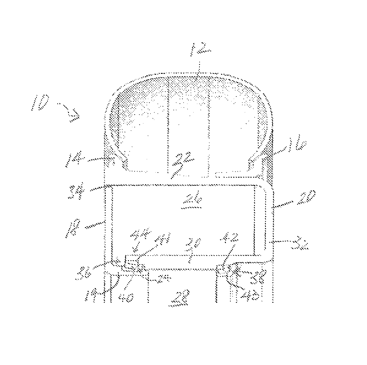
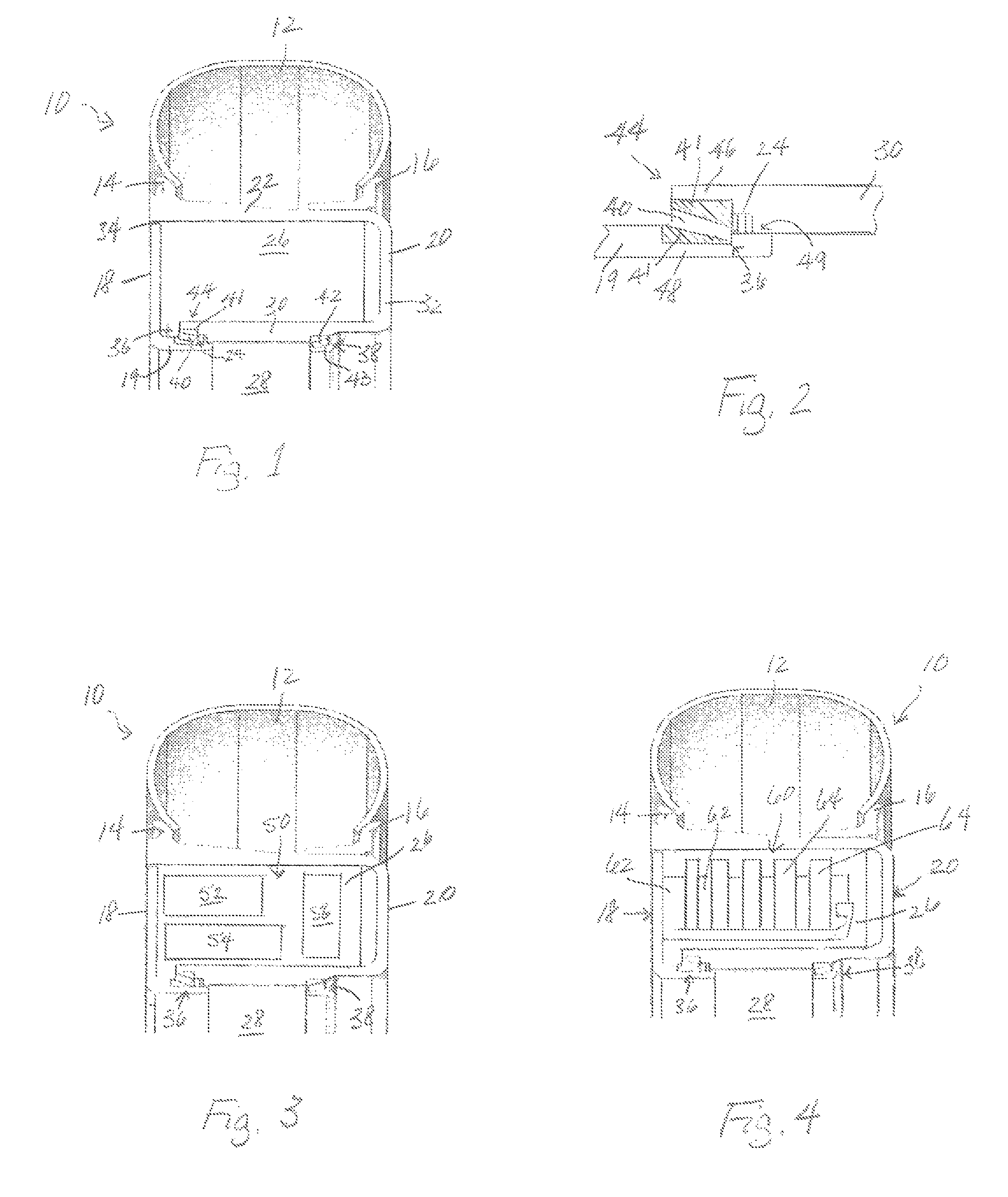
[0020]The present invention provides a bearing arrangement for an aircraft landing gear wheel that is designed to provide not only effective bearing support for the wheel and any structures associated with the wheel, but to maximize the internal volume within the wheel available for mounting structures within the landing gear wheel. The arrangement shown and described herein may expand both radial and axial dimensions to expand the internal volume of the wheel cavity. This expanded volume allows the effective mounting and support of drive means structures in an aircraft equipped with onboard non-engine drive means controllable to drive the wheel and move the aircraft on a ground surface without reliance on the aircraft's main engines. The expanded volume may also allow the effective mounting and support of wheel brakes within landing gear wheels not equipped with drive means.

[0021]Referring to the drawings, FIG. 1 shows a cross-sectional view of a portion of an aircraft landing gear...


PUM


Abstract

A bearing arrangement for an aircraft landing gear wheel is provided that effectively supports the wheel on an axle while maximizing internal wheel volume available for mounting a non-engine drive motor used to power the wheel and / or brakes or other structures within the maximized wheel volume. The bearing arrangement is preferably employed with a two-part aircraft wheel mounted on a landing gear axle and includes bearing structures located only on wheel sections adjacent to the axle. A specifically configured cantilevered joint portion of inboard and outboard wheel sections supports weight and loads bearing structures, eliminating the need for and space required by a high speed bearing. Stiffness necessary for strength and structural integrity is provided by the materials selected to form the wheel sections.

Description

PRIORITY CLAIM[0001]This application claims priority from U.S. Provisional Application No. 61 / 641,868, filed May 2, 2012, the disclosure of which is fully incorporated herein.TECHNICAL FIELD[0002]The present invention relates generally to aircraft wheel bearings and specifically to an arrangement of aircraft wheel bearings that maximizes usable space within an aircraft landing gear wheel.BACKGROUND OF THE INVENTION[0003]Aircraft wheels are currently designed primarily in response to requirements for accommodating selected tires as well as housing the aircraft's brakes and supporting the aircraft on a ground surface. A goal is to accomplish these functions with a wheel design that adds a minimum amount of weight to the aircraft while maximizing wheel operational life. Aircraft wheels not only help support the aircraft's weight during taxi, but, along with other landing gear structures, are required to absorb significant loads when an aircraft lands. The conditions under which aircraf...

Claims


Application Information

Patent Timeline
Patent Type & Authority Patents(United States)
IPC IPC(8): B60B19/00B60B27/00B60B37/10B60B19/06B64C25/40B64C25/36B60B25/04
CPCB60B27/001B60B19/06B60B27/0047B60B27/0078B60B37/10B64C25/36B64C25/405B60B25/04B60B2380/14B60B2380/64B60B2900/311B60B2900/351B60Y2200/51Y02T50/823Y02T50/80B64C25/40
Inventor PERKINS, SCOTT
Owner BOREALIS TECH LTD
Learn More