Diffuser with strut-induced vortex mixing

a technology of vortex mixing and diffuser, which is applied in the direction of machines/engines, mechanical equipment, engine manufacture, etc., can solve the problems of less than optimal flow conditions, radially distorted flow entering the diffuser, and radially non-uniform velocity distribution entering the diffuser, etc., and achieves the effect of increasing mechanical stiffness

Inactive Publication Date: 2016-11-15
SIEMENS AG
View PDF19 Cites 8 Cited by
  • Summary
  • Abstract
  • Description
  • Claims
  • Application Information

AI Technical Summary

Benefits of technology

[0022]The strut structure may include a planar divider, lying in an axially and circumferentially extending plane intersecting a span-wise transition between the first and second span-wise portions limiting radial flow and increasing mechanical stiffness between the first and second span-wise portions.

Problems solved by technology

Various changes in the operation of the gas turbine engine may result in less than optimum flow conditions at the diffuser inlet and, in particular, can result in radially distorted flow entering the diffuser.
For example, operation at an off-design operating point, e.g., part load operation or an off-design ambient air inlet temperature, may result in a radially non-uniform velocity distribution entering the diffuser.
Also, redesigns of an existing engine, such as to increase the output of the engine, may result in less than optimal flow conditions at the diffuser inlet if structure controlling flow into the diffuser is not reconfigured for changes affecting flow conditions through the engine.

Method used


Image

  • Diffuser with strut-induced vortex mixing
  • Diffuser with strut-induced vortex mixing
  • Diffuser with strut-induced vortex mixing

Examples


Embodiment Construction

[0033]In the following detailed description of the preferred embodiment, reference is made to the accompanying drawings that form a part hereof, and in which is shown by way of illustration, and not by way of limitation, a specific preferred embodiment in which the invention may be practiced. It is to be understood that other embodiments may be utilized and that changes may be made without departing from the spirit and scope of the present invention.

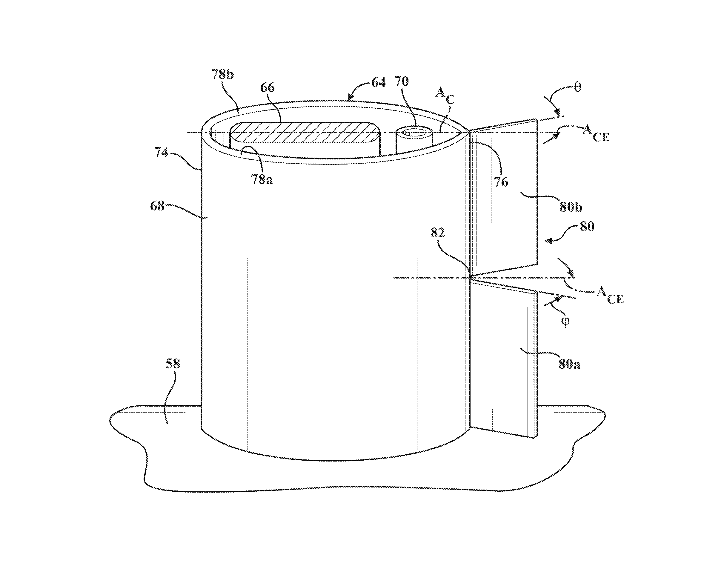
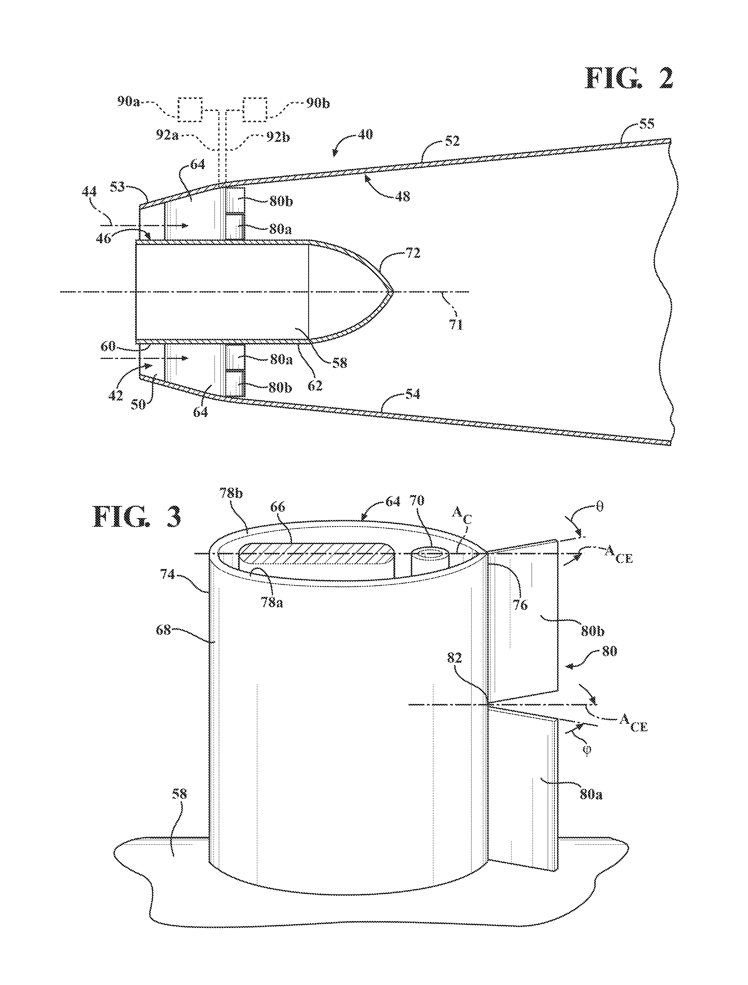
[0034]In accordance with an aspect of an invention, a diffuser design is described to provide an improved diffuser performance by providing increased radial mixing of flow passing through the diffuser, including an improved uniformity of the flow velocity distribution between radially inner and outer regions of the diffuser. In an exemplary application of the diffuser described herein, a common occurrence of a hub-strong velocity profile may be addressed by the present invention by creation of a swirling flow that causes higher velocity ...


PUM


Abstract

A gas turbine engine includes inner and outer shrouds forming an annular gas path, and a plurality of struts connecting the inner shroud to the outer shroud. Airfoil shaped shields surround the struts, and each of the shields include a main body having an upstream leading edge defining a chordal axis extending in a downstream axial direction from the leading edge toward a downstream end of the shield. A trailing edge flap is located at the downstream end of each shield, the trailing edge flap including first and second span-wise portions. The first span-wise portion is oriented to direct flow at an angle relative to the chordal axis of the main body and the second span-wise portion is oriented to direct flow in a direction that is at a different angle than the angle of first span-wise portion.

Description

FIELD OF THE INVENTION[0001]The invention relates in general to turbine engines and, more particularly, to exhaust diffusers for turbine engines.BACKGROUND OF THE INVENTION[0002]Referring to FIG. 1, a turbine engine 10 generally includes a compressor section 12, a combustor section 14, a turbine section 16 and an exhaust section 18. In operation, the compressor section 12 can induct ambient air and can compress it. The compressed air from the compressor section 12 can enter one or more combustors 20 in the combustor section 14. The compressed air can be mixed with the fuel, and the air-fuel mixture can be burned in the combustors 20 to form a hot working gas. The hot gas can be routed to the turbine section 16 where it is expanded through alternating rows of stationary airfoils and rotating airfoils and used to generate power that can drive a rotor 26. The expanded gas exiting the turbine section 16 can be exhausted from the engine 10 via the exhaust section 18.[0003]The exhaust sec...

Claims


Application Information

Patent Timeline
Patent Type & Authority Patents(United States)
IPC IPC(8): F01D25/30F01D17/14F01D17/16
CPCF01D25/30F01D17/143F01D17/16F05D2220/32F05D2240/122F05D2240/127F05D2250/70
Inventor OROSA, JOHN A.
Owner SIEMENS AG
Why Eureka
Try Eureka