Rolling boot with transition region

a transition region and rolling boot technology, applied in the direction of yielding couplings, mechanical equipment, rotary machine parts, etc., can solve the problems of a1 reducing the stability of rolling boots in use, and achieve the effect of increasing form stability, increasing form stability, and preventing the disassembly of inner parts of joints

Active Publication Date: 2016-11-15
GKN DRIVELINE INT GMBH
View PDF12 Cites 13 Cited by
  • Summary
  • Abstract
  • Description
  • Claims
  • Application Information

AI Technical Summary

Benefits of technology

[0008]Accordingly, disclosed herein is a rolling boot as well as a plunge joint and a joint arrangement comprising such a rolling boot showing increased form stability compared to rolling boots known from the state of the art.
[0019]An advantage of the presently disclosed boot is that it provides for an increased form stability, including if no outer or inner reinforcing ribs are present. However, outer and / or inner reinforcing ribs may be present between the first fold and the transition region, or within the first fold, or between the first and the second fold within the boot, respectively. The reinforcing ribs may be arranged, for example, alternatively within the boot and outside the boot. It is also possible that only outer reinforcing ribs, or only inner reinforcing ribs, are present. For example, 6, 8, 10, or 12 outer and / or inner reinforcing ribs may be present.
[0020]Further due to said increased form stability, a disassembly of the inner parts of a joint is hindered, i.e., due to the high retention force imparted by the boot of the present disclosure. Thus, the risk of disassembly of the inner parts of a joint through bending or plunging at high angles will be diminished.
[0025]By the provision of said second transition region, the boot will be in a position to brace against the shaft, without creating negative effects such as knocking within the joint agreement.
[0029]The variation of the thickness of the boot material, e.g., in the regions as defined before, allows a fine tuning of the retention force, and, thus, the form stability of the boot claimed. The boot in use provides for two different ranges of operation that may be measured and visualized in a force / path diagram. For example, a first range A of operation exists, where in use the forces, especially the axial force, will only increase slightly, whereas a second range of operation B immediately neighbouring said first range of operation will be present in which the forces, especially the axial force, will increase drastically, practically ad infinitum. Due to said second range of operation B, the boot in accordance with the present disclosure will have the ability for axial centering of shafts in joints, especially plunge joints. The variation of the thickness of the boot material, especially in the regions as mentioned before, will allow also a fine tuning of said force / path abilities, i.e., of the first and the second range of operation, of the claimed boot.

Problems solved by technology

However, due to said special design, the rolling boot disclosed in WO 2009 / 155955 A1 has a decreased form stability in use, especially at higher revolutions per minute.

Method used


Image

  • Rolling boot with transition region
  • Rolling boot with transition region
  • Rolling boot with transition region

Examples


first embodiment

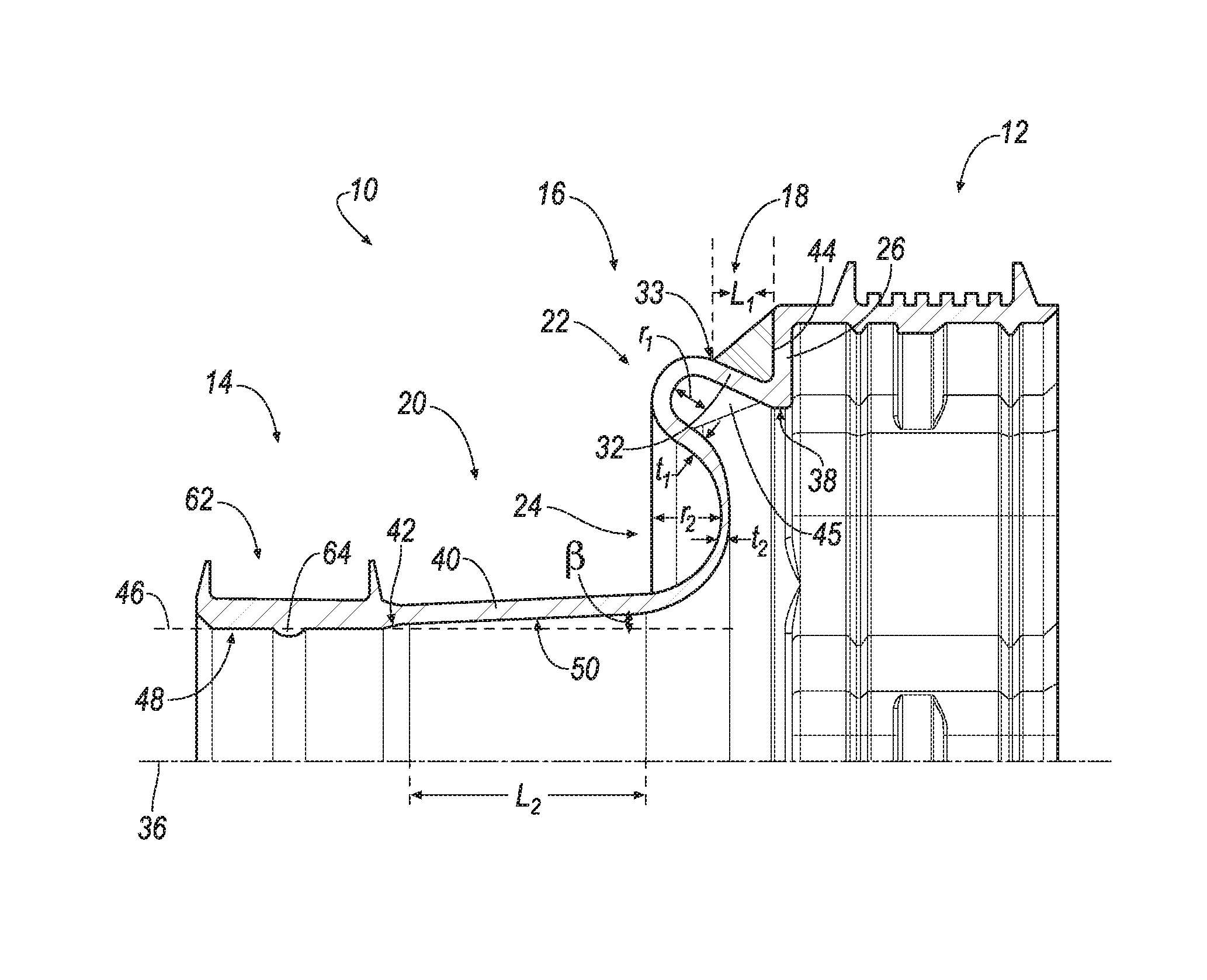
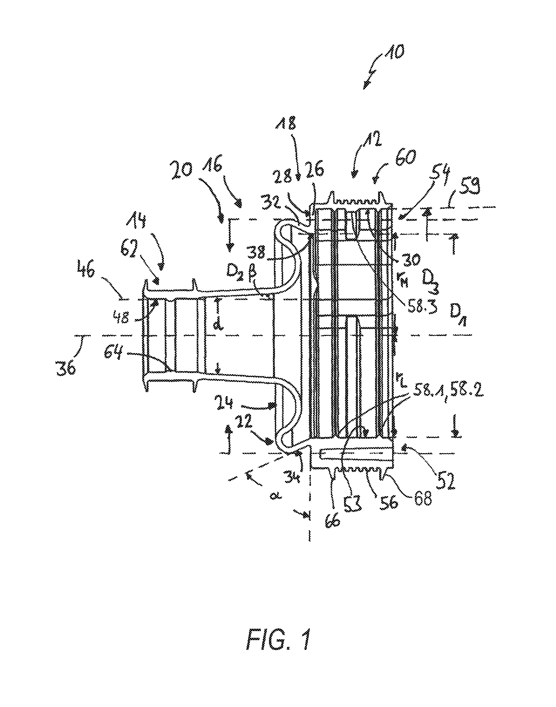
[0067]Referring now to the drawings where alike reference numerals are used to identify identical components in the various views, FIG. 1 illustrates a sectional view along a longitudinal main axis 36 of a rolling boot 10. Said rolling boot 10 comprises a first fastening region 12 for fixing the boot 10 to a joint casing (not shown), and a second fastening region 14 for fastening the boot 10 to the shaft (not shown). When the mounting boot 10 via the first fastening region 12 and the second fastening region 14 on a joint casing and shaft, respectively, binder elements, especially tensioning elements, are used.

[0068]The first fastening region 12 provides for a binder seat region 60, in which the binder element, especially tensioning element, may be placed. On the outside of said binder seat region 60, outer ribs 56 are located, providing for a binder seat surface, having all identical shape, e.g., a square-like shape in the longitudinal section as shown in FIG. 1. On the other side o...

third embodiment

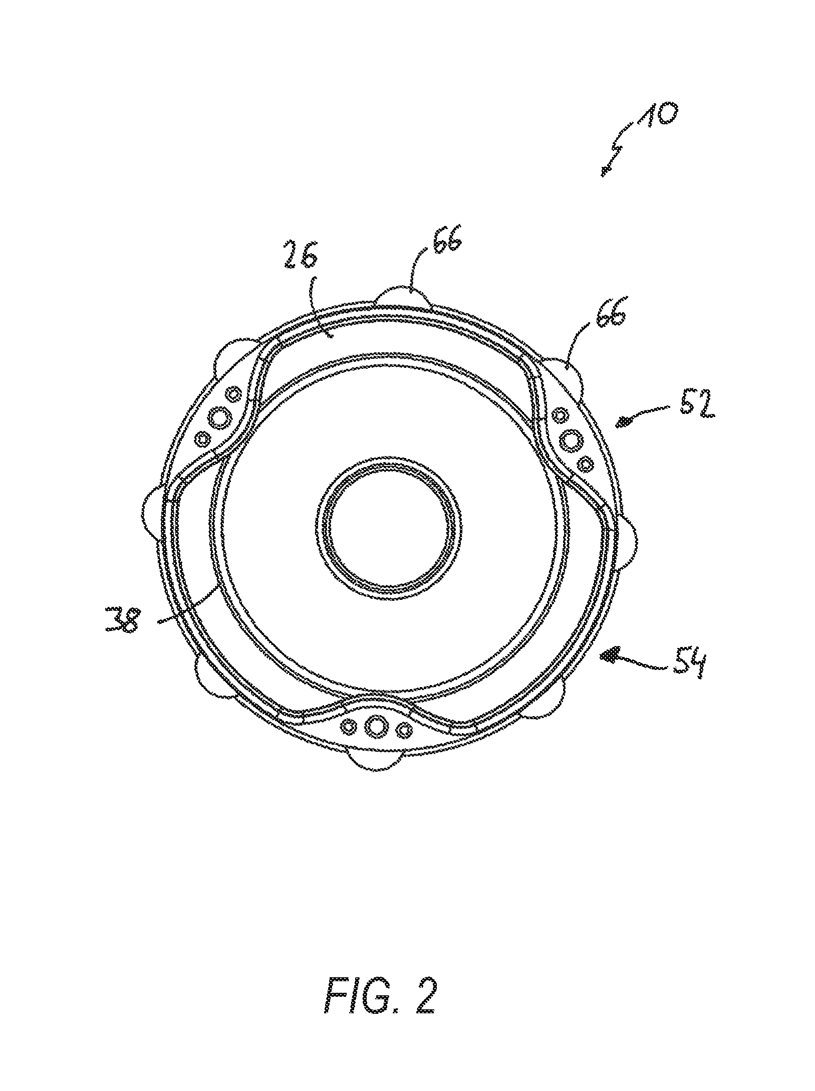
[0082]FIG. 4 shows a joint arrangement in part in accordance with a third embodiment, including a shaft 74 being mounted in a joint arrangement 72 with a plunge joint 70 with a casing 82, and a boot 10. No binder element for fixing the boot 10 on the plunge joint 70 is shown in FIG. 4. Boot 10 is not mounted under tension. It can be seen that the bottom 38 of first flange 26 of the first transition region protrudes the front edge of the plunge joint 70 in the un-lobe regions 54, whereas no such protuberance are present in the lobe regions 52.

[0083]FIG. 5 is an axial force-plunge path-diagram of the boot, showing two different ranges of operation, namely a first range of operation A where a movement of about 25 mm only leads to a small increase of the axial force, whereas in a second range of operation B, a drastic increase of the axial force over a length of less than 7 mm occurs. In the second range of operation, the boot is fully extended at the end. In this position, the boot is ...

fourth embodiment

[0085]FIG. 7 shows a joint arrangement in accordance with a fourth embodiment, showing a shaft 74 assembled with two tripode plunge joints 70.1 and 70.2. Rolling boots 10.1 and 10.2 are mounted without any tension on joint casings 82.1 and 82.2, respectively. Axial movement and retention force is, thus, distributed in an essentially equal way on each of the rolling boots 10.1, and 10.2, respectively. The shaft 74 is axially centered within the plunge joints 70.1 and 70.2 due to the high retention forces imparted by boots 10.1 and 10.2, respectively.


PUM


Abstract

A rolling boot comprises a first fastening region for fastening the boot to a joint casing, a second fastening region for fastening the boot to a shaft, and a fold region between the first and the second fastening region with a first fold near to the first fastening region and a second fold near to the second fastening region. The boot further comprises, between the first fastening region and the first fold, a first transition region comprising a first flange neighboring the first fastening region with a bottom. A ratio between a first minimal diameter D1, defined by the bottom of the first flange of the first transition region, and a second maximal diameter D2, defined by the first fold, where both are viewed in a longitudinal section direction along the main axis, is between approximately 1:1.01 to approximately 1:1.25.

Description

CROSS-REFERENCE TO RELATED APPLICATIONS[0001]This application is a continuation application of, and accordingly claims priority to, PCT International Application No. PCT / EP2012 / 002108 (filed May 16, 2012), the entire contents of which prior application is incorporated herein by reference.BACKGROUND AND SUMMARY[0002]A rolling boot comprises a first fastening region for fastening the boot to a joint casing, a second fastening region for fastening the boot to a shaft, and a fold region between the first and the second fastening region with a first fold near to the first fastening region and a second fold near to the second fastening region. Further disclosed is a plunge joint with a rolling boot in accordance with the present disclosure, as well as a joint arrangement with at least one rolling boot, and a shaft.[0003]Rolling boots in accordance with the present disclosure may be used especially for plunge joints, for example in the form of a ball-and-socket joint or trilobe joint, and ...

Claims


Application Information

Patent Timeline
Patent Type & Authority Patents(United States)
IPC IPC(8): F16D3/84F16D3/205
CPCF16D3/845F16D3/2055Y10S464/905
Inventor SCHUMACHER, RALFBUSCH, WINFRIEDDEISINGER, MARKUSWETTE, JOACHIMHILDEBRANDT, WOLFGANGSCHAFFERUS, THOMASSCHMEINK, ACHIM
Owner GKN DRIVELINE INT GMBH
Why Eureka
Try Eureka