Magnetic orthodontic assembly

a magnetic and orthodontic technology, applied in the field of magnetic orthodontic assembly, can solve the problems of pain, cuts or discomfort, time-consuming and laborious process of attaching components to patients' teeth,

Inactive Publication Date: 2016-11-22
PATEL RUCHIR RAMESH
View PDF20 Cites 48 Cited by
  • Summary
  • Abstract
  • Description
  • Claims
  • Application Information

AI Technical Summary

Benefits of technology

[0010]Accordingly, there is provided an improved orthodontic assembly that is suitable for aligning teeth with minimal attachment to the patient.

Problems solved by technology

Attaching the components to a patient's teeth is a time-consuming and tedious process requiring multiple sessions between a patient and orthodontist.
Higher discomfort levels than aligner or removable appliance and restriction of certain kind of foods is also a negative for fixed orthodontic treatment, such as braces.
Given the numerous meetings between patient and orthodontist, discomfort to the wearer, and some emergencies with poking wire or broken brackets, the experience of orthodontic treatment with braces can be unpleasant.
As slack develops the ends of the archwire can extend past the last bracket, or tube, installed on the patient's teeth, and the free end(s) of the archwire can cause cuts or discomfort.
In addition, braces using exterior brackets also tend to interfere with a patient's ability to brush, floss, and perform other dental hygiene.
The Invisalign and other aligner-based treatment often takes longer than the traditional fixed wire brace system to correct initial crowding or rotations of teeth if crowding and rotations are moderate to severe.
Other disadvantages of aligner-based systems occur in that the patient's teeth (mostly the lateral incisors in the upper arch and the lower incisors) lose tracking of the aligners due to their shape and size, and new impressions or digital dental scans are needed during mid treatment if patient's aligners are not fitting well.
It is also hard to extrude teeth; i.e., to bring teeth toward the biting surface from the gum surface using such a system, as no wires attached to selected teeth are utilized and hence, it is difficult to develop an ideal extrusion force on a selected tooth.
In fact, aligner systems accomplish their goals, but it takes an extensive time period and a number of trays to extrude teeth, correct rotations and resolve tooth crowding that is moderate to severe.

Method used


Image

  • Magnetic orthodontic assembly
  • Magnetic orthodontic assembly
  • Magnetic orthodontic assembly

Examples


Embodiment Construction

[0064]While the present disclosure may be susceptible to embodiment in different forms, there is shown in the Figures, and will be described herein in detail, specific embodiments, with the understanding that the disclosure is to be considered an exemplification of the principles of the present disclosure, and is not intended to limit the present disclosure to that as illustrated.

[0065]In the illustrated embodiments, directional representations—i.e., up, down, left, right, front, rear and the like, used for explaining the structure and movement of the various elements of the present disclosure, are relative. These representations are appropriate when the elements are in the position shown in the Figures. If the description of the position of the elements changes, however, it is assumed that these representations are to be changed accordingly.

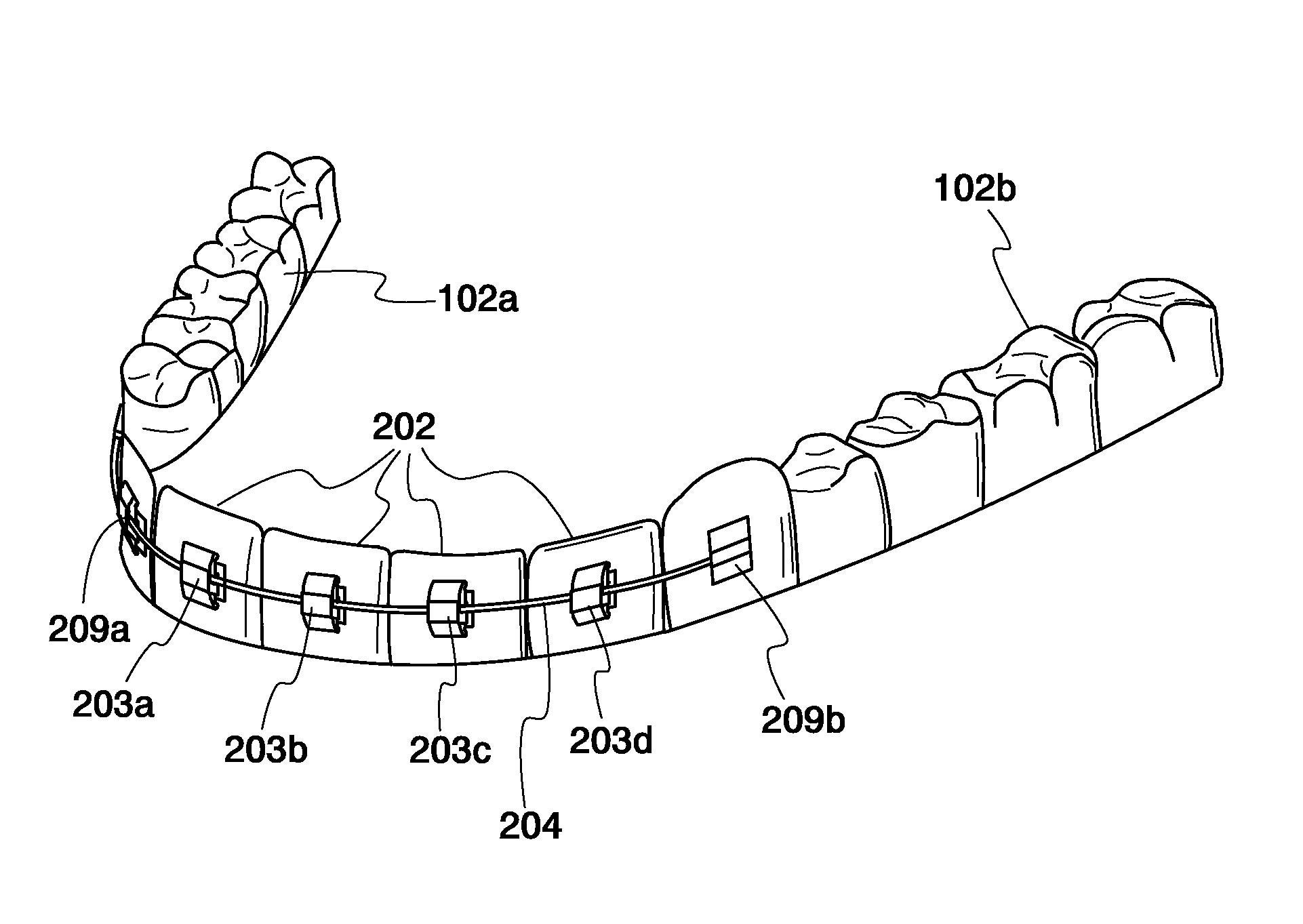
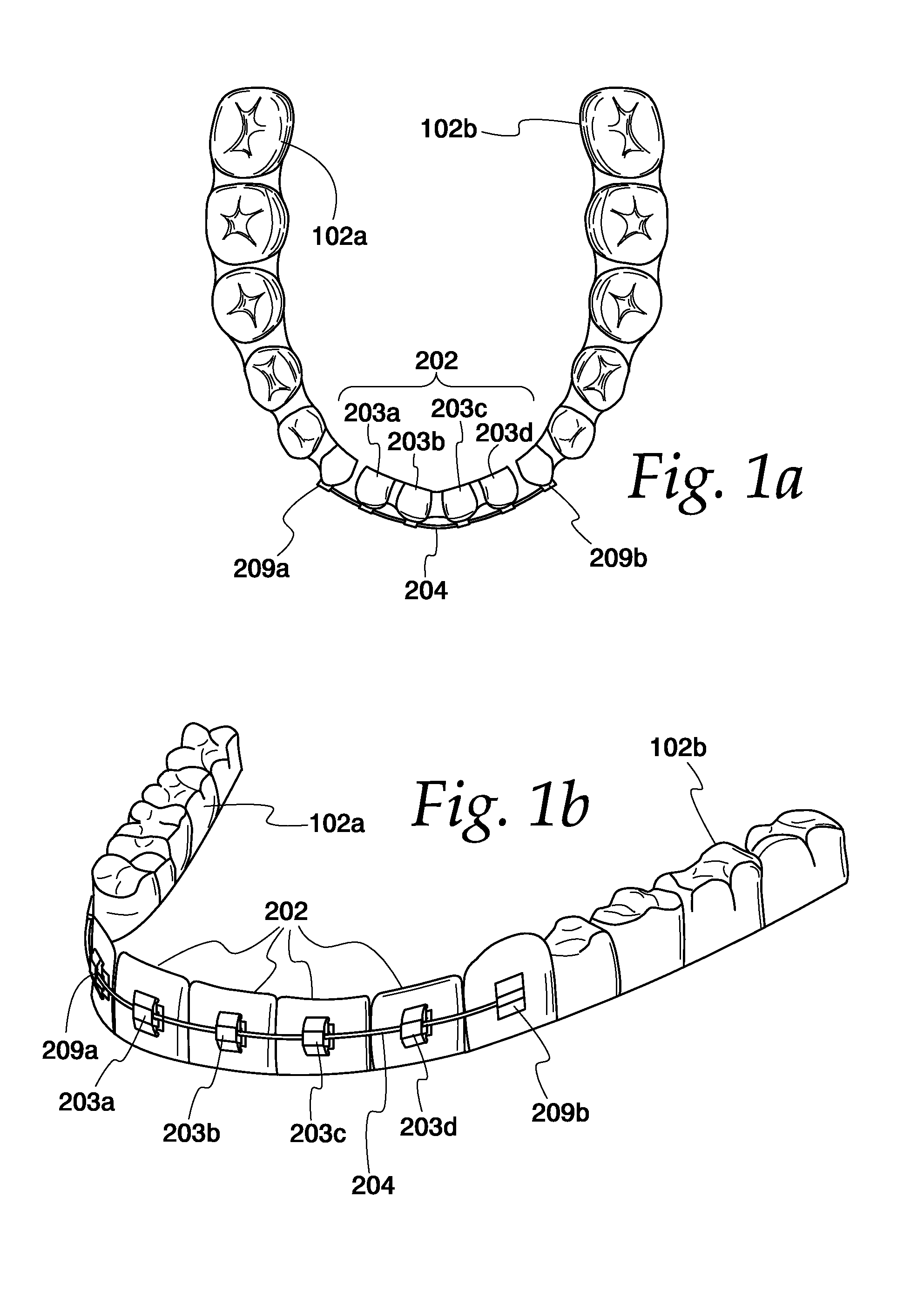
[0066]Turning to the Figures and to FIG. 1A in particular, a top plan view of a part of a system for moving teeth is illustrated. In specific, ...


PUM


Abstract

An orthodontic assembly for moving selected teeth of a patient includes a hollow aligner shell that fits over a set of selected teeth. The aligner shell supports a series of tooth moving elements, such as magnets or metal engagement plates that are fixed in place in alignment with the selected teeth. Metal plates or magnets are affixed to the selected teeth and when the aligner shell is fitted over the teeth, the magnets in the shell exert attraction or repulsion forces on the metal plates to move the selected teeth in accordance with a treatment protocol.

Description

REFERENCE TO RELATED APPLICATIONS[0001]This application is a continuation-in-part application of prior U.S. non-provisional patent application Ser. No. 14 / 262,843, filed Apr. 28, 2014 and entitled “System For Moving and Aligning Teeth.” I hereby claim priority to said Ser. No. 14 / 262,843 under 35 U.S.C. §120. I also claim priority to prior U.S. provisional patent application Ser. No. 62 / 064,218, filed Oct. 15, 2014 for “Magnetic Orthodontic Appliance.”BACKGROUND OF THE DISCLOSURE[0002]The present disclosure relates generally orthodontic devices and assemblies. More particularly, the present disclosure relates to an assembly applied to a patient's teeth or repositioning the patient's teeth through the application of modest force on out-of-position, or out of occlusion teeth so that the out-of-position teeth are moved from their initial position to a final position.[0003]Repositioning teeth for aesthetic or other functional or hygiene purposes is generally accomplished through the use...

Claims


Application Information

Patent Timeline
Patent Type & Authority Patents(United States)
IPC IPC(8): A61C7/00A61C7/08
CPCA61C7/006A61C7/08A61C7/14A61C7/143A61C7/28A61C7/287
Inventor PATEL, RUCHIR RAMESH
Owner PATEL RUCHIR RAMESH
Why Eureka
Try Eureka