Systems and methods for detecting the onset of compressor stall

a compressor and stall detection technology, applied in the field of gas turbine engines, can solve the problems of loss of efficiency, unsatisfactory compressor stall, adversely affecting the efficiency of gas turbines,

Active Publication Date: 2016-11-22
GENERAL ELECTRIC CO
View PDF26 Cites 3 Cited by
  • Summary
  • Abstract
  • Description
  • Claims
  • Application Information

AI Technical Summary

Problems solved by technology

However, if the pressure ratio is allowed to exceed a certain critical value during turbine operation, an undesirable condition known as compressor stall may occur.
Compressor stall may reduce the compressor pressure ratio and reduce the airflow delivered to a combustor, thereby adversely affecting the efficiency of the gas turbine.
Following rotating stall, the compressor may transition into a surge condition or a deep stall condition that may result in a loss of efficiency and, if allowed to be prolonged, may lead to catastrophic failure of the gas turbine.

Method used


Image

  • Systems and methods for detecting the onset of compressor stall
  • Systems and methods for detecting the onset of compressor stall
  • Systems and methods for detecting the onset of compressor stall

Examples


Embodiment Construction

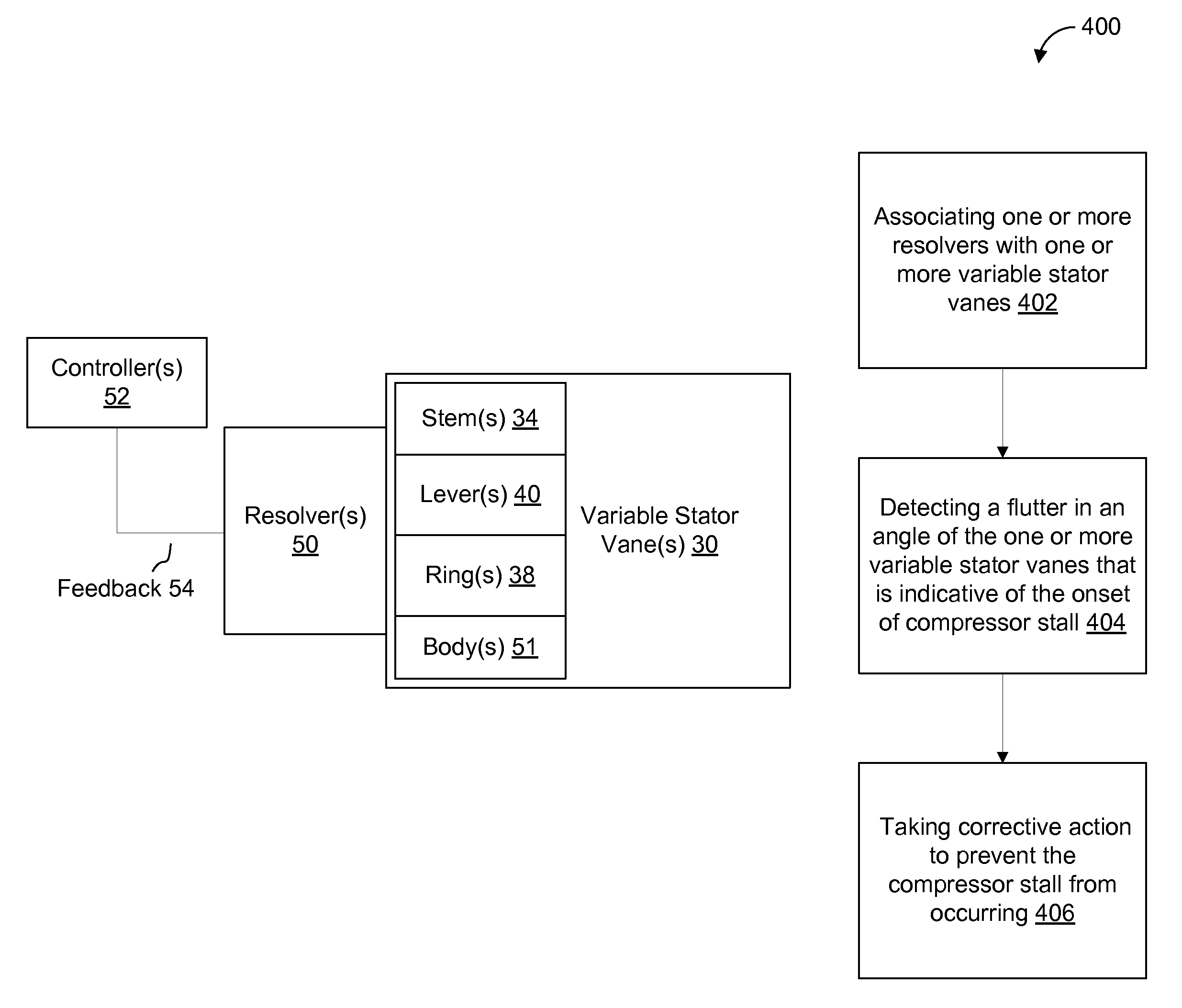
[0014]Illustrative embodiments will now be described more fully hereinafter with reference to the accompanying drawings, in which some, but not all embodiments are shown. The present application may be embodied in many different forms and should not be construed as limited to the embodiments set forth herein. Like numbers refer to like elements throughout.

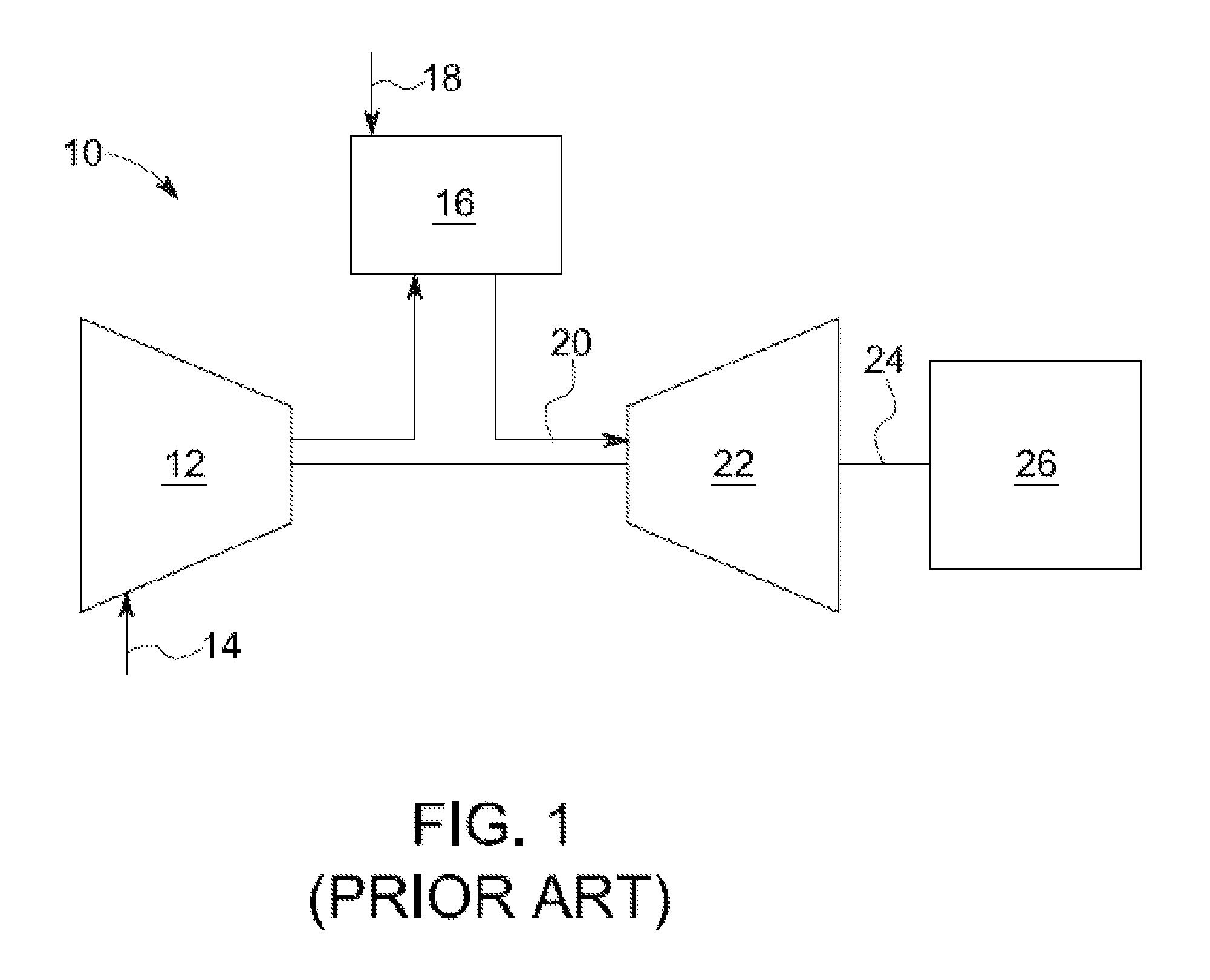
[0015]Illustrative embodiments are directed to, among other things, systems and methods for detecting compressor stall in gas turbine engines. FIG. 1 shows an example schematic view of a gas turbine engine 10 as may be used herein. As is known, the gas turbine engine 10 may include a compressor 12. The compressor 12 compresses an incoming flow of air 14. The compressor 12 delivers the compressed flow of air 14 to a combustor 16. The combustor 16 mixes the compressed flow of air 14 with a pressurized flow of fuel 18 and ignites the mixture to create a flow of combustion gases 20. Although only a single combustor 16 is shown, the gas...


PUM


Abstract

Embodiments of the present application include a stall detection system for a gas turbine engine. The system may include a compressor and a number of variable stator vanes associated with the compressor. The variable stator vanes may form one or more variable stator vane stages. The system may also include one or more resolvers associated with one or more of the variable stator vanes. The resolvers may be configured to detect a flutter in an angle of the variable stator vanes. The flutter may be indicative of the onset of compressor stall.

Description

FIELD OF THE DISCLOSURE[0001]Embodiments of the present application relate generally to gas turbine engines and more particularly to systems and methods for detecting the onset of compressor stall.BACKGROUND OF THE DISCLOSURE[0002]During operation of a gas turbine engine using a multi-stage axial compressor, a turbine rotor is turned at high speeds by a turbine so that air is continuously induced into the compressor. The air is accelerated by rotating blades and swept rearwards onto adjacent rows of variable stator vanes. Each rotor blade / variable stator vane stage increases the pressure of the air.[0003]In addition to translating the kinetic energy of the air into pressure, the variable stator vanes also serve to correct the deflection given to the air by the rotor blades and to present the air at the correct angle to the next stage of rotor blades. Pivoting the variable stator vanes permits the flow capacity of the compressor or turbine to be changed, thereby ensuring that the flo...

Claims


Application Information

Patent Timeline
Patent Type & Authority Patents(United States)
IPC IPC(8): F02C9/20F04D27/02F04D29/56F04D27/00
CPCF04D27/0246F02C9/20F04D27/001F04D29/563F05D2270/101
Inventor RITTENHOUSE, BRIAN ALLEN
Owner GENERAL ELECTRIC CO
Why Eureka
Try Eureka