White key of keyboard instrument

a keyboard instrument and white key technology, applied in the field of white keys of keyboard instruments, can solve the problems of causing greater noise, achieve the effects of preventing the warp of the white key, reducing or increasing the weight difference between the right and left portions with respect to the center line, and reducing or increasing the weight differen

Active Publication Date: 2016-11-29
YAMAHA CORP
View PDF5 Cites 0 Cited by
  • Summary
  • Abstract
  • Description
  • Claims
  • Application Information

AI Technical Summary

Benefits of technology

[0008]In the white key disclosed in Patent Document 2, the side wall not provided with the gate and the side wall provided with the gate are different from each other in thickness in the narrow segment. This construction is for preventing the warp of the white key by equalizing the time required for cooling and solidifying among the right and left portions. Thus, a difference in weight between the right and left portions with respect to the center line may be reduced or increased depending upon whether the gate is provided in one or the other of the pair of side walls. In the where the difference in weight between the right and left portions is large, depression and release of the white key cause greater vibration thereof than in the above-described case, so that greater noises are caused by the contact and collision of the white key with the key guide and / or an adjacent one of the other white keys and the black keys.
[0009]This invention has been developed in view of the above-described situations, and it is an object of the present invention to provide a white key of a keyboard instrument which reduces vibrations during depression or release of the white key.

Problems solved by technology

In the white key of this kind, accordingly, loads to be imposed on the respective right and left portions with respect to the center line are not balanced, and when depressed or released, the white key may vibrate and come into contact and collision with a key guide provided on the key frame for guiding the depression and release of the white key and / or with an adjacent one of the other white keys and the black keys, which may cause noises.
In the where the difference in weight between the right and left portions is large, depression and release of the white key cause greater vibration thereof than in the above-described case, so that greater noises are caused by the contact and collision of the white key with the key guide and / or an adjacent one of the other white keys and the black keys.

Method used


Image

  • White key of keyboard instrument
  • White key of keyboard instrument
  • White key of keyboard instrument

Examples


first embodiment

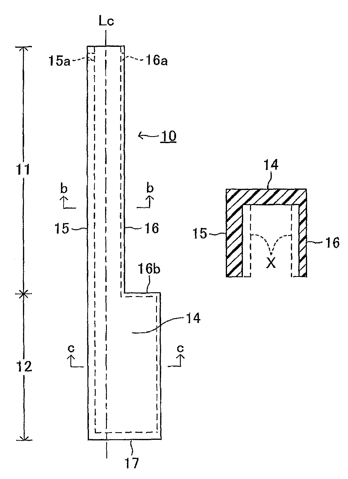
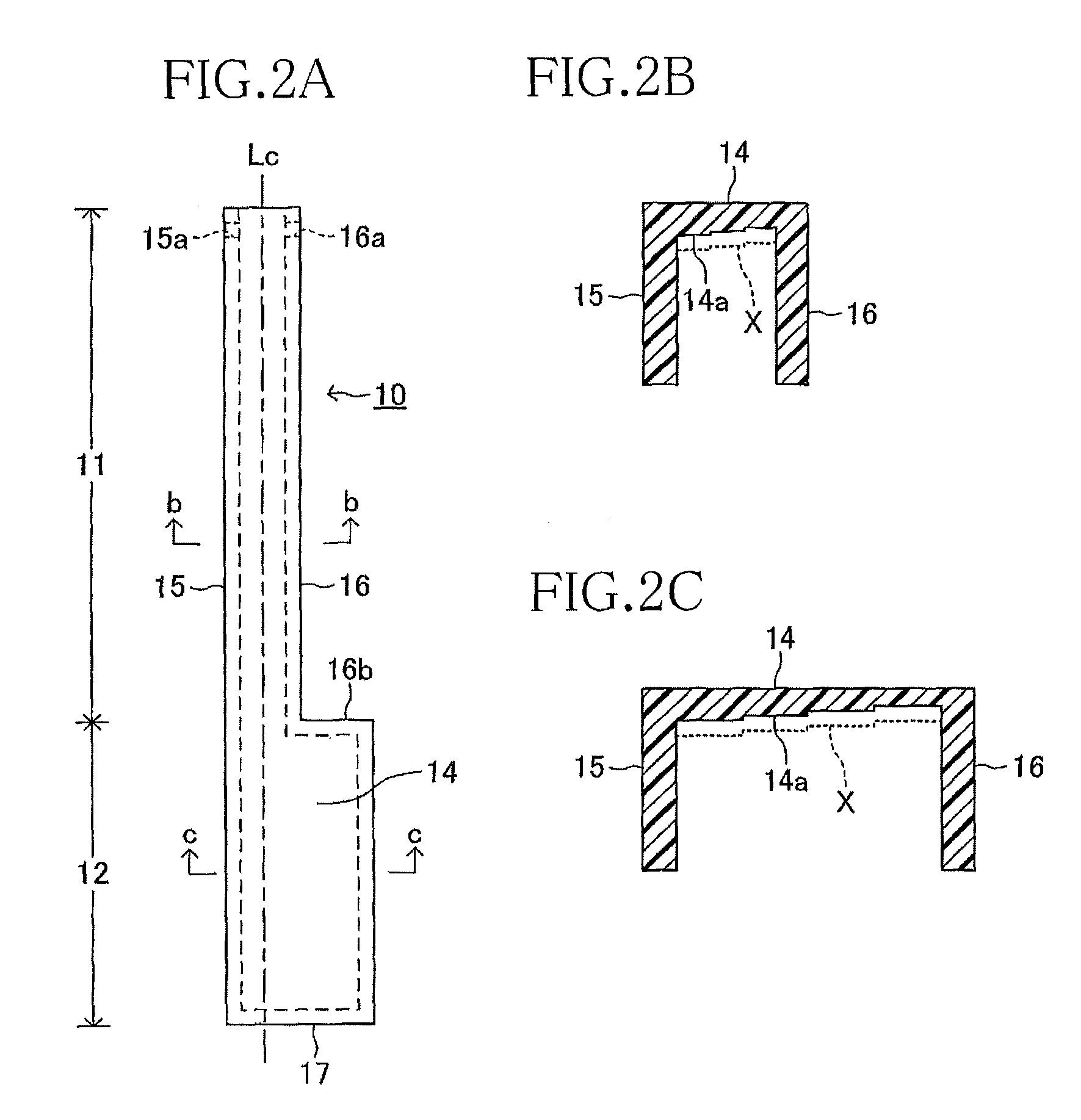
[0023]There will be next explained white keys 10 according to a first embodiment of the present invention with reference to FIGS. 2A-2C. FIG. 2A is a plan view illustrating the white keys 10 respectively corresponding to C and F, in each of which the difference in weight between the right and left portions of the white key 10 with respect to the center line Lc is large. FIG. 2B is a cross-sectional view taken along line b-b in FIG. 2A, and FIG. 2C is a cross-sectional view taken along line c-c in FIG. 2A.

[0024]Each white key 10 includes an upper wall 14, a left side wall 15, a right side wall 16, and a front wall 17 and is formed with an inner space having a square shape opening downward. These upper wall 14, the left side wall 15, the right side wall 16, and the front wall 17 are formed of resin and molded in one piece so as to each have a planar plate shape. The respective rear end portions of the left side wall 15 and the right side wall 16 have through holes 15a, 16a through whi...

second embodiment

[0031]There will be next explained white keys 10 according to a second embodiment with reference to FIGS. 3A-3C. As in the first embodiment, FIG. 3A is a plan view illustrating the white keys 10 respectively corresponding to C and E FIG. 3B is a cross-sectional view taken along line b-b in FIG. 3A, and FIG. 3C is a cross-sectional view taken along line c-c in FIG. 3A. This second embodiment and the first embodiment are different from each other only in the thicknesses of the upper wall 14, the left side wall 15, and the right side wall 16 and are the same as each other in the other construction. Thus, the same reference numerals as used in the first embodiment are used to designate the corresponding elements of the second embodiment, and an explanation of which is dispensed with.

[0032]In this second embodiment, the upper wall 14 and the front wall 17 have the same thickness, but the thickness of the left side wall 15 differs from that of the right side wall 16. Specifically, the thi...

third embodiment

[0038]There will be next explained white keys 10 according to a third embodiment with reference to FIGS. 4A-4D. As in the first and second embodiments, FIG. 4A is a plan view illustrating the white keys 10 respectively corresponding to C and F. FIG. 4B is a cross-sectional view taken along line b-b in FIG. 4A, and FIG. 4C is a cross-sectional view taken along line c-c in FIG. 4A. This third embodiment is principally the same as the first and second embodiments in construction. Thus, the same reference numerals as used in the first and second embodiments are used to designate the corresponding elements of the third embodiment, and an explanation of which is dispensed with.

[0039]In this third embodiment, the upper wall 14, the left side wall 15, the right side wall 16, and the front wall 17 have the same thickness. A weight 31 elongated in the front and rear direction is bonded and fixed by adhesive to a left edge portion of the inside surface 14a of the upper wall 14 (i.e., a portion...


PUM


Abstract

A white key of a keyboard instrument includes: an upper wall elongated in a front and rear direction; and a pair of side walls extending downward respectively from right and left edges of the upper wall and each elongated in the front and rear direction. The upper wall and the pair of side walls define an inner space opening downward. The upper wall and the pair of side walls include: a narrow portion and a wide portion wider in a right and left direction. The white key has right and left portions with respect to a center line of the narrow portion. The right and left portions are different in construction to adjust a balance of load between the right and left portions with respect to the center line.

Description

CROSS REFERENCE TO RELATED APPLICATION[0001]The present application claims priority from Japanese Patent Application No. 2014-208134, which was filed on Oct. 9, 2014, the disclosure of which is herein incorporated by reference in its entirety.BACKGROUND[0002]Technical Field[0003]The following disclosure relates to a white key of a keyboard instrument.[0004]Description of the Related Art[0005]Patent Document 1 (Japanese Patent Application Publication No. 2007-139885) discloses white and black keys each including: an upper wall elongated in a front and rear direction; and a pair of side walls extending downward respectively from right and left edges of the upper wall and each elongated in the front and rear direction, and the upper wall and the pair of side walls are formed of resin in one piece so as to have an inner space opening downward. In this example, the upper wall and the side walls have the same thickness.[0006]Patent Document 2 (Japanese Unexamined Utility Model Application...

Claims


Application Information

Patent Timeline
Patent Type & Authority Patents(United States)
IPC IPC(8): G10C3/12
CPCG10C3/12
Inventor YAMAMOTO, SHIN
Owner YAMAHA CORP
Why Eureka
Try Eureka