Antenna system and method for reporting receiving power of the same

a technology of reference signal and receiving power, which is applied in the direction of power management, transmission monitoring, wireless commuication services, etc., can solve the problems of unbalanced power, enb cannot obtain information, and flexibly allocate resources, so as to improve system throughput and flexible transportation point selection and resource allocation

Active Publication Date: 2016-11-29
ALCATEL LUCENT SAS
View PDF18 Cites 0 Cited by
  • Summary
  • Abstract
  • Description
  • Claims
  • Application Information

AI Technical Summary

Benefits of technology

[0008]An objective of the present invention is to provide an antenna system and a method for reporting receiving power of the same, to make the technical solution for solving the problem of unbalanced power feasible.
[0015]Compared with the prior art, the antenna system and the method for reporting RSRP of the same provided by the present invention enable an eNB to obtain reference signal power of all transport points used for a UE, that is, know channel information of path loss of each distributed antenna, so that the problem of unbalance power can be solved by a corresponding means. Moreover, the eNB can further implement more flexible transport point selection and resource allocation, implement necessary power control, and improve the system throughput.

Problems solved by technology

The DAS is different from a conventional centralized wire system in that, path loss from distributed antenna ports at different geographical positions to a user equipment (UE) is different, thereby often causing the problem of unbalanced power.
These technical solutions require channel information of path loss of different transport points; however, in the current DAS, the eNB cannot obtain the information.
In fact, since the eNB cannot know the channel information of path loss of each distributed antenna, other problems, such as being inconvenient for transport point selection, being incapable of flexibly allocating resources, and reducing the system throughput, may be caused.

Method used


Image

  • Antenna system and method for reporting receiving power of the same
  • Antenna system and method for reporting receiving power of the same
  • Antenna system and method for reporting receiving power of the same

Examples


Embodiment Construction

[0021]In order to better understand the spirit of the present invention, the present invention is further described below using a combination of selected preferred embodiments.

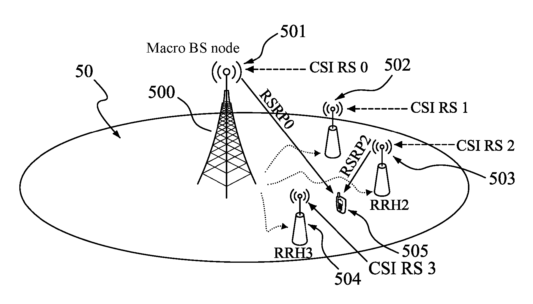
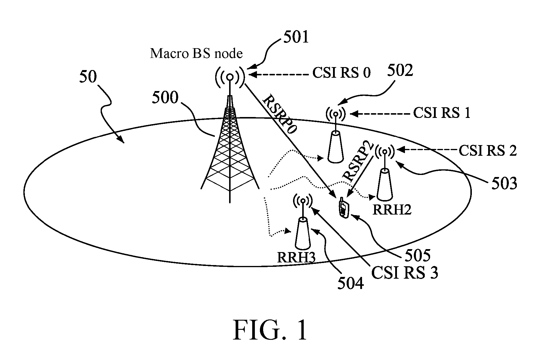
[0022]The Long Term Evolution (LTE) project is the largest new technology research and development project started by the 3rd Generation Partnership Project (3GPP) in recent years. This technology based on Orthogonal Frequency Division Multiplexing / Frequency Division Multiple Access (OFDM / FDMA) is regarded as a quasi-4G technology. The LTE will be the main wide area broadband mobile communication system worldwide, and in the future, all the 2G / 3G / 3.5G technologies will evolve to the LTE / LTE-Advanced (LTE-A) phase. At present, multiple LTE standard versions exist in the industry, but none of them solve the problem of unbalanced power in the DAS, thereby hindering further improvement and implementation of the technology.

[0023]It should be noted that, due to the development of the technology and the update of the...


PUM


Abstract

An antenna system and a method for reporting enhanced Reference Signal Receiving Power (eRSRP) of the same are provided. According to an embodiment of the present invention, the method for reporting eRSRP includes: transmitting, by an evolved Node Base (eNB), different reference signals to different transport points being distributed; measuring, by a user equipment (UE), eRSRP of the different transport points; and reporting, by the UE, the measured eRSRP of the different transport points to the eNB. Compared with the prior art, the eNB can obtain channel information of path loss of each transport point, to fundamentally solve the problem of unbalanced power, and can perform other optimization operations based on the information to improve the system throughput and other performance.

Description

BACKGROUND OF THE INVENTION[0001]1. Field of the Invention[0002]The present invention relates to an antenna system and a method for reporting Reference Signal Receiving Power (RSRP) of the same, and more particularly to a distributed antenna system (DAS) and a method for reporting RSRP of the same.[0003]2. Description of the Prior Art[0004]In downlink Multiple Input Multiple Output (MIMO), a typical case of a DAS is deploying distributed antennas for indoor and outdoor use. The DAS is different from a conventional centralized wire system in that, path loss from distributed antenna ports at different geographical positions to a user equipment (UE) is different, thereby often causing the problem of unbalanced power. In order to solve the problem of unbalanced power, some technical solutions of adjustment and improvement may be performed at an evolved Node Base (eNB) side, in which the technical solutions include power compensation, transport point selection, and the like. These techni...

Claims


Application Information

Patent Timeline
Patent Type & Authority Patents(United States)
IPC IPC(8): H04W4/00H04W52/04H04W52/38H04W52/40H04B17/318H04W52/24
CPCH04W52/04H04B17/318H04W52/242H04W52/245H04W52/386H04W52/40
Inventor SHE, FENGYANG, HONGWEIDENG, YUN
Owner ALCATEL LUCENT SAS
Why Eureka
Try Eureka