Refrigerant jacket and air conditioning apparatus equipped therewith

a technology of refrigerant jackets and air conditioners, which is applied in the direction of lighting and heating apparatus, domestic cooling apparatus, semiconductor/solid-state device details, etc., can solve the problems of faulty fastening of the cover member to the refrigerant cooling member, and the failure to obtain the required refrigerant cooling performan

Active Publication Date: 2016-11-29
DAIKIN IND LTD
View PDF14 Cites 2 Cited by
  • Summary
  • Abstract
  • Description
  • Claims
  • Application Information

AI Technical Summary

Benefits of technology

[0008]For this reason, ensuring that the threads of the cover member fixing screw hole do not strip even due to repeated screwing and excessive tightening of the cover member fixing screw and making it possible for the cover member to be fixed to the refrigerant cooling member in a state in which the refrigerant tube and the groove portions of the refrigerant cooling member are in sufficiently close contact with one another is preferred.
[0025]Because of this, here, the threads of the cover member fixing screw hole no longer strip even due to repeated screwing and excessive tightening of the cover member fixing screw, and the cover member can be fixed to the refrigerant cooling member in a state in which the refrigerant tube and the groove portion of the refrigerant cooling member are in sufficiently close contact with one another.

Problems solved by technology

However, in this screwing structure, sometimes the threads of the cover member fixing screw hole end up stripping due to repeated screwing and excessive tightening of the cover member fixing screw, so that faulty fastening of the cover member to the refrigerant cooling member occurs.
Additionally, when such faulty fastening occurs, the close contact between the refrigerant tube and the groove portions of the refrigerant cooling member becomes insufficient, and there is the concern that the required refrigerant cooling performance will not be obtained.

Method used


Image

  • Refrigerant jacket and air conditioning apparatus equipped therewith
  • Refrigerant jacket and air conditioning apparatus equipped therewith
  • Refrigerant jacket and air conditioning apparatus equipped therewith

Examples


Embodiment Construction

)

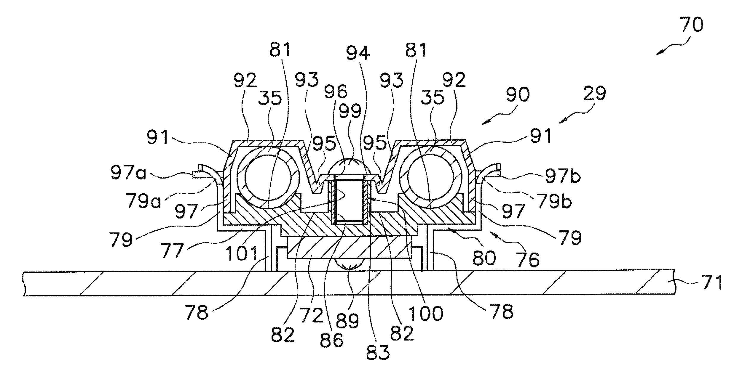
[0042]An embodiment of a refrigerant jacket pertaining to the present invention and an air conditioning apparatus equipped therewith, as well as an example modification thereof, will be described below on the basis of the drawings. The specific configurations of the refrigerant jacket pertaining to the present invention and the air conditioning apparatus equipped therewith are not limited to the configurations in the following embodiment and example modification thereof and can be changed without departing from the gist of the invention.

(1) Configuration of Air Conditioning Apparatus

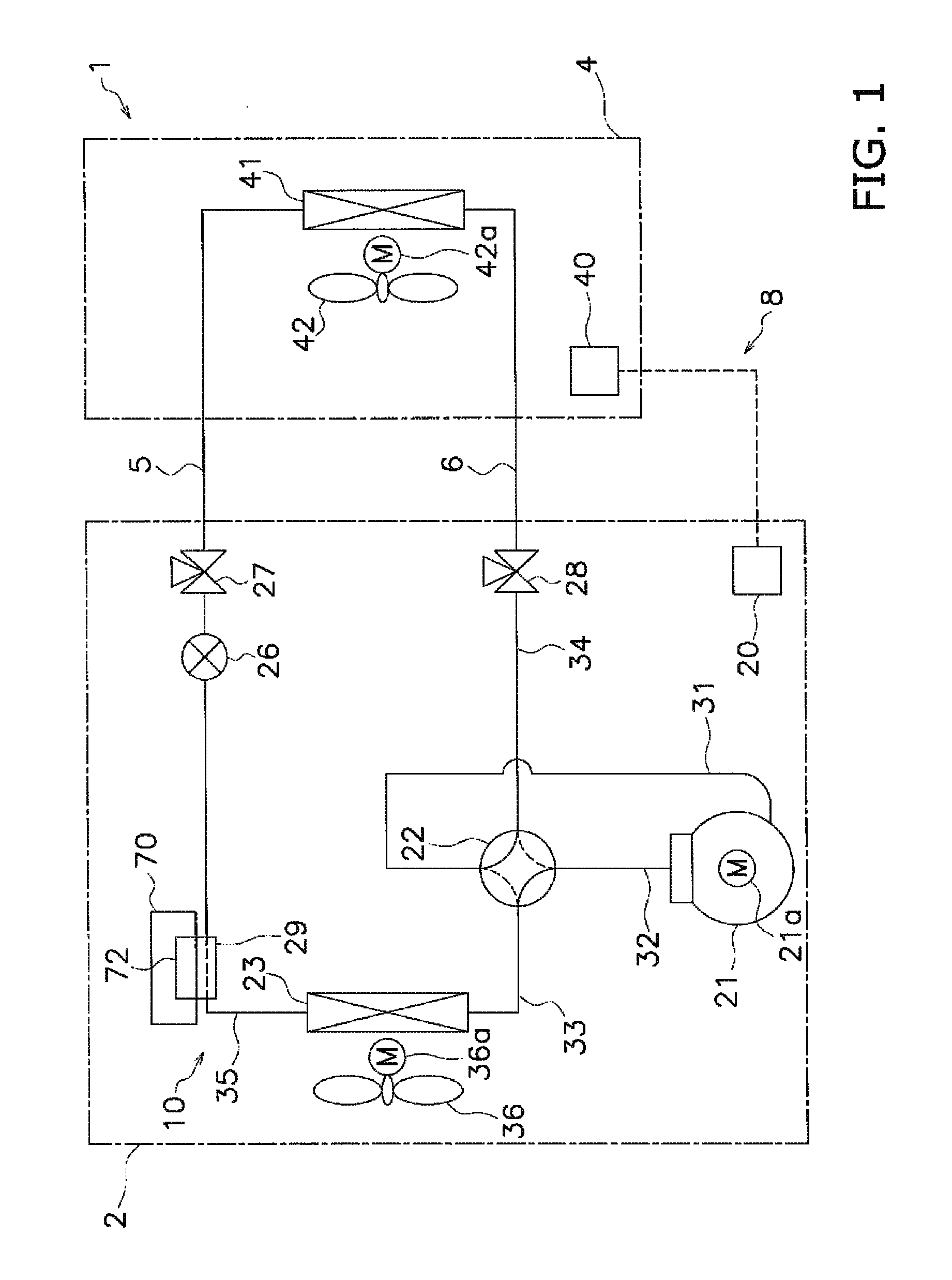
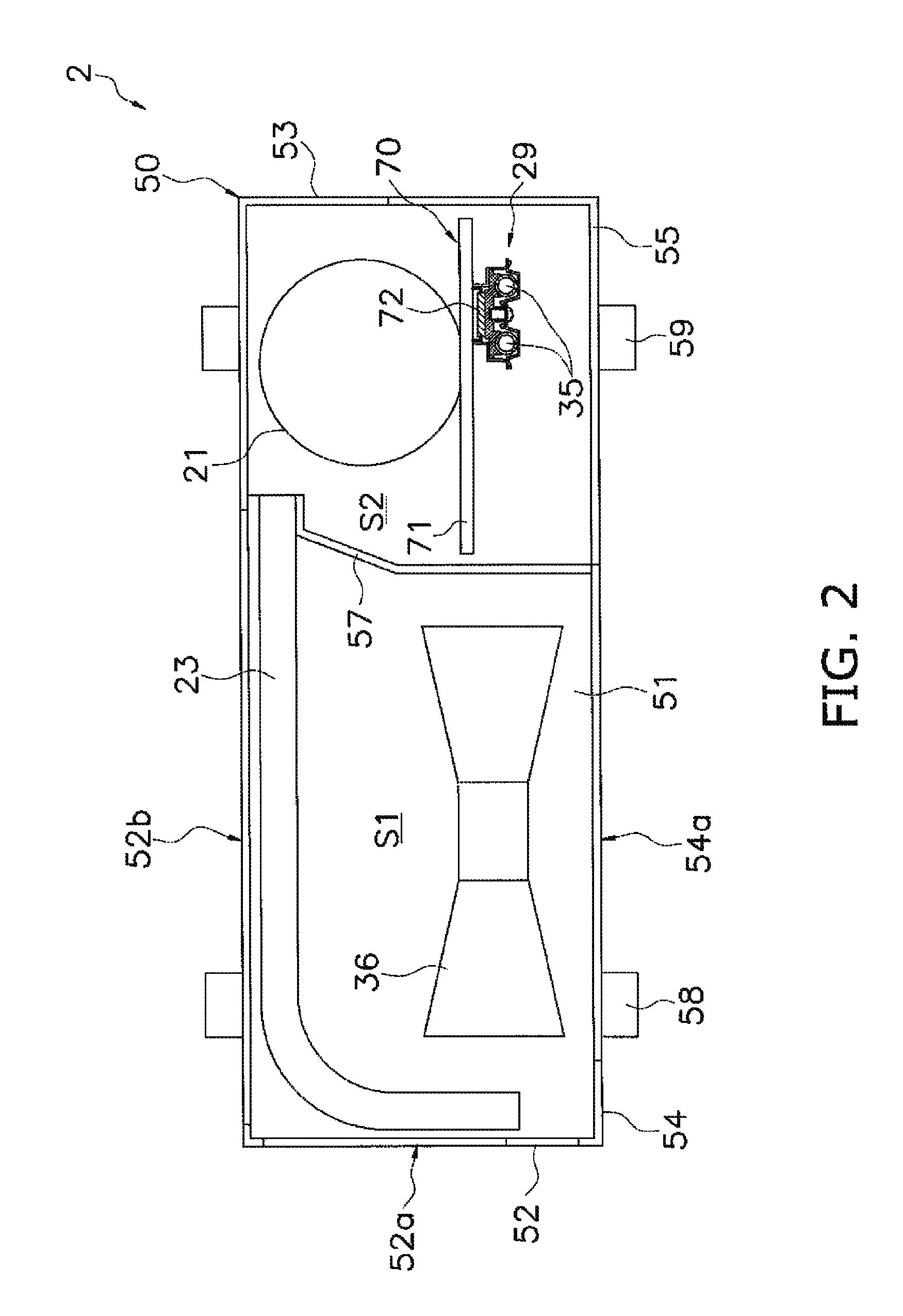
[0043]FIG. 1 is a schematic configuration diagram of an air conditioning apparatus 1 equipped with a refrigerant jacket pertaining to the present invention.

[0044]The air conditioning apparatus 1 is an apparatus that can cool and heat a room in a building or the like by performing a vapor compression refrigeration cycle. The air conditioning apparatus 1 is configured mainly as a result of an outdoor unit...


PUM


Abstract

A refrigerant jacket includes a refrigerant cooling member, a cover member and a strength member. The cooling member is constructed of aluminum or aluminum alloy that thermally contacts a heat emitting electrical part, and has a groove portion. A refrigerant tube of a refrigerant circuit fits into the groove portion. The cover member covers the refrigerant cooling member in a state where the refrigerant tube has been fitted into the groove portion. The strength member is higher in strength than the cooling member, and is fixed to the cooling member. The cover member has a cover-side through hole opposing the strength member. The strength member has a cover member fixing screw hole opposing the cover-side through hole. The cover member is fixed to the strength member by a cover member fixing screw that passes through the cover-side through hole and screws into threads of the cover member fixing screw hole.

Description

BACKGROUND OF THE INVENTION[0001]Field of the Invention[0002]The present invention relates to a refrigerant jacket and to an air conditioning apparatus equipped therewith, and particularly relates to a refrigerant jacket that uses refrigerant circulating through a refrigerant circuit to cool a heat emitting electrical part and to an air conditioning apparatus equipped therewith.[0003]Background Art[0004]Conventionally, a refrigerant jacket that uses refrigerant circulating through a refrigerant circuit to cool a heat emitting electrical part and an air conditioning apparatus equipped therewith have been known, such as those described in Japanese Patent Application Laid-open No. 2013-42115.[0005]The refrigerant jacket has a refrigerant cooling member and a cover member. The refrigerant cooling member is a member made of aluminum that thermally contacts the heat emitting electrical part and in which are formed groove portions into which a refrigerant tube configuring the refrigerant c...

Claims


Application Information

Patent Timeline
Patent Type & Authority Patents(United States)
IPC IPC(8): F25D23/12H01L23/40H01L31/052H01L33/64H05K7/20H01L23/473
CPCH05K7/20254H01L23/40H01L23/473H01L31/052H01L33/648H05K7/20309H05K7/20409H05K7/20418H05K7/20445H01L2023/4087H01L2924/0002H01L2924/00Y02E10/50
Inventor FUJIWARA, MASAHIDEISHIZEKI, SHINICHITAOKA, KENTAROHNOMURA, SHINICHIROUIKEDA, MOTONOBUDOHMAE, HIROSHI
Owner DAIKIN IND LTD
Why Eureka
Try Eureka