Control unit for centralizing control by grouping a plurality of paths
a control unit and plurality of paths technology, applied in the field of control units, can solve the problems of difficult creation of coordinated sequence programs, high cost, and high effort in constructing the system, and achieve the effect of easy coordination between paths
- Summary
- Abstract
- Description
- Claims
- Application Information
AI Technical Summary
Benefits of technology
Problems solved by technology
Method used
Image
Examples
embodiment 1
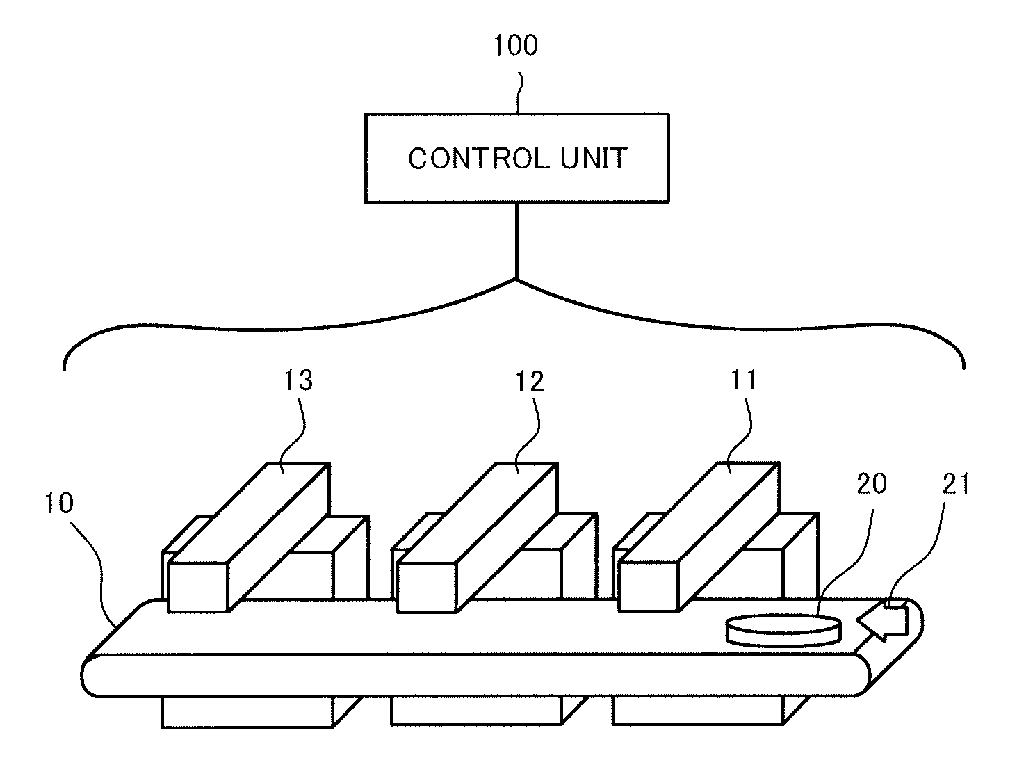
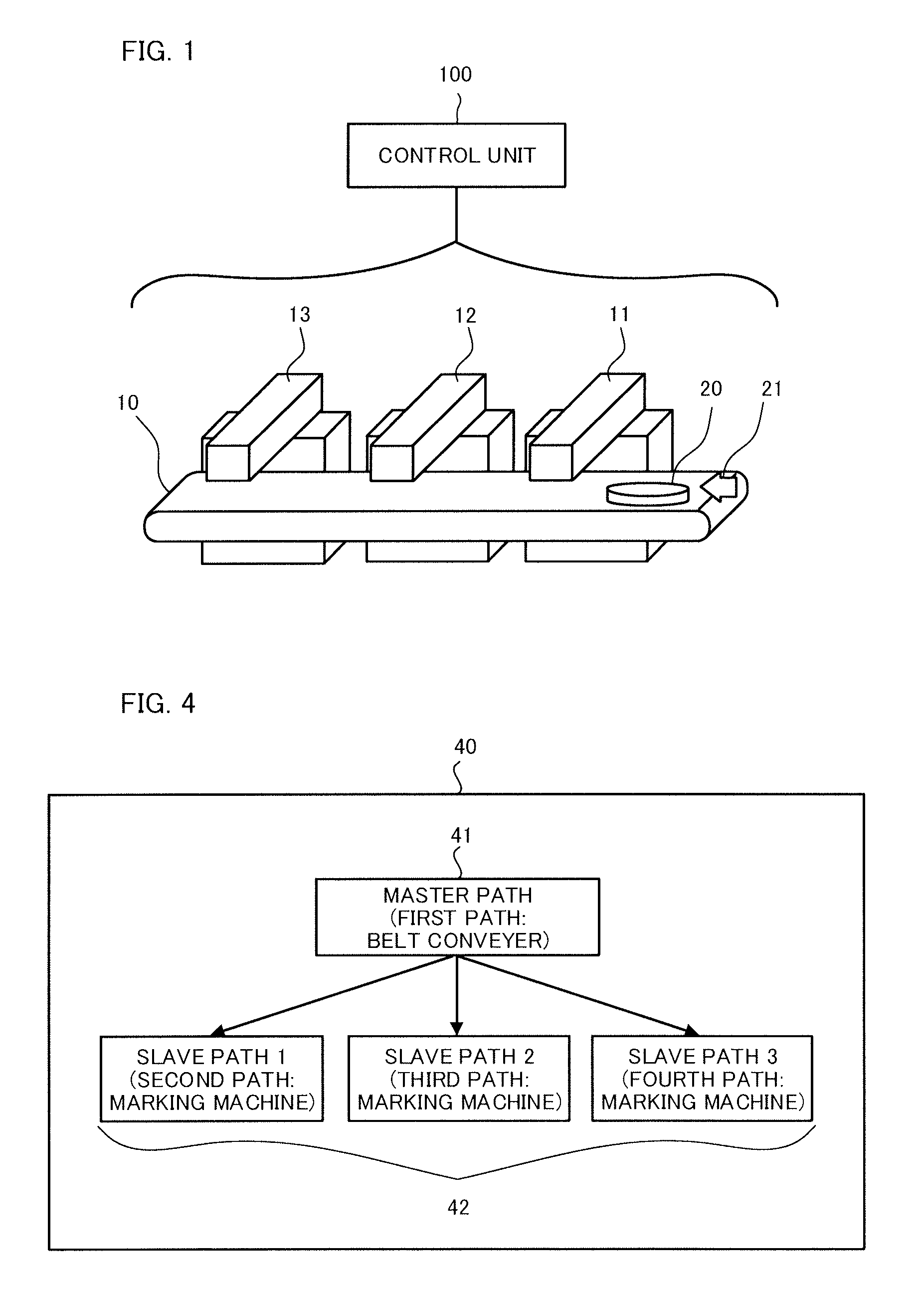
[0044]A system including a belt conveyer and three marking machines shown in FIG. 1 will be described as an example. This system includes the belt conveyer 10, the first marking machine 11, the second marking machine 12, a third marking machine 13, and a control unit 100 that controls the belt conveyer 10, the first marking machine 11, the second marking machine 12, and the third marking machine 13.
[0045]For example, when the speed of the belt conveyer 10 changes at an arbitrary timing, the first to third marking machines 11, 12, and 13 also need to change their speeds in sync with the belt conveyer 10. If the first to third marking machines 11, 12, and 13 do not change their speed, they cannot perform marking at correct positions.
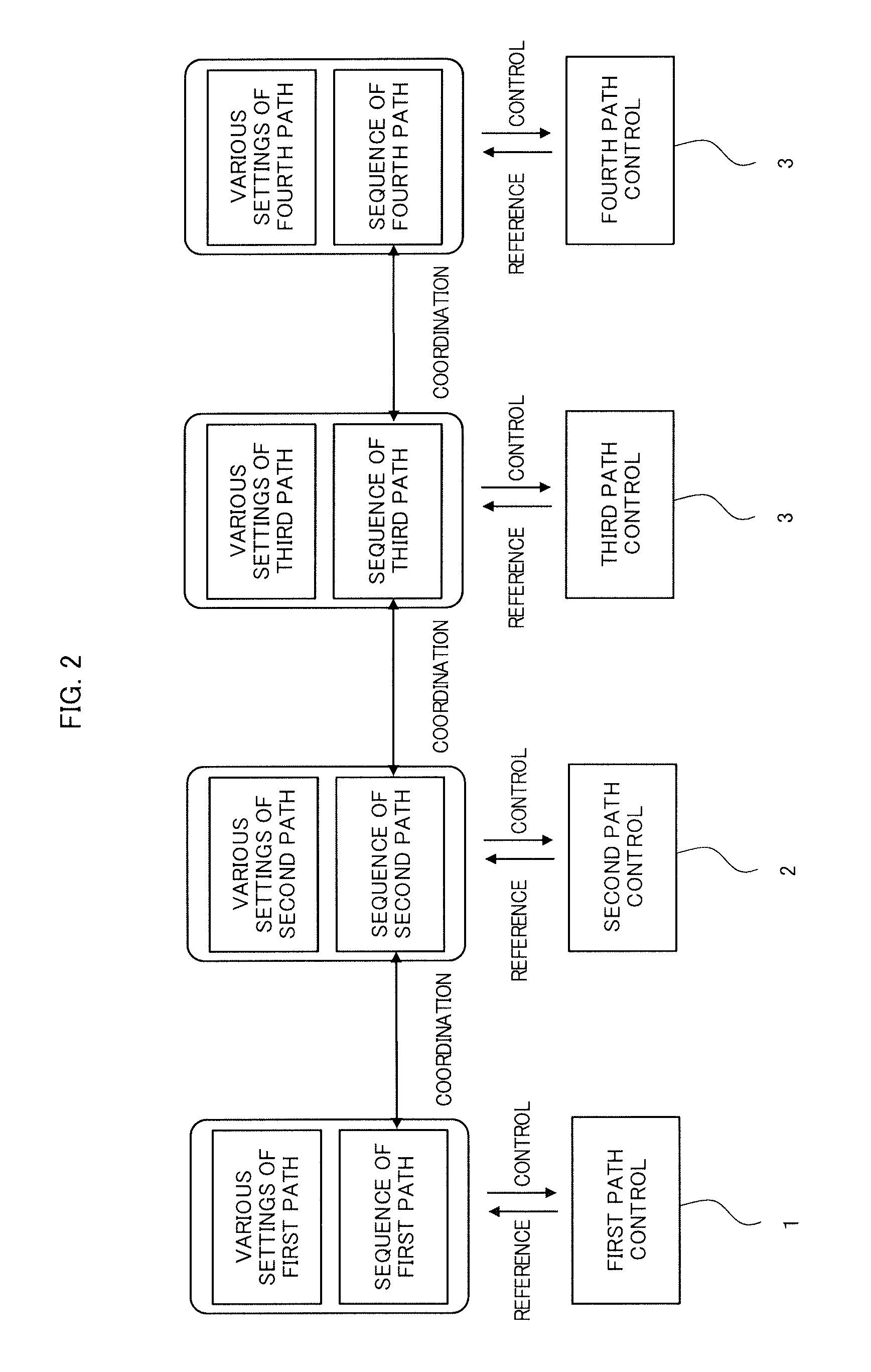
[0046]As shown in FIG. 2, if first path control 1 is set to control the belt conveyer 10 and second path control 2, third path control 3, and fourth path control 4 are set to control a first marking machine 11, a second marking machine 12, and a third mark...
example
[0051]For a program command that moves a shaft at 1000 millimeters per minute, when there is a setting for an override control signal that increases the speed to 250% and performs execution and a setting of a parameter for limiting the maximum speed to 2000 millimeters per minute, the shaft moves at 2000 millimeters per minute as a result of analyzing these settings.
[0052]In the example shown in FIG. 5, the following input, conversion, limitation, and output are performed. Program command analysis: A speed command of 1000 millimeters per minute is input.[0053]Control signal analysis: The speed command is changed to 2500 millimeters per minute.[0054]Control parameter analysis: The speed command is limited to 2000 millimeters per minute.[0055]Final output: The axis of motor rotates at 2000 millimeters per minute.
[0056]FIG. 6 shows path control according to the embodiment of the present invention. This path control is performed by a control unit that controls a machine tools or industr...
embodiment 2
[0062]The machine structure may be changed depending on the use situation of the machine. For example, although the three marking machines are present in the machine structure shown in embodiment 1 above, the number of marking machines required may be increased or reduced because, for example, the target object is changed.
[0063]FIG. 7A shows the machine structure before being changed and FIG. 7B shows the machine structure after being changed. It is assumed that there are the belt conveyer 10 and the first to third marking machines 11, 12, and 13 as shown in FIG. 7A before the machine structure is changed and that there are the belt conveyer 10 and the first to fourth marking machines 11, 12, 13, and 14 as shown in FIG. 7B after the machine structure is changed. In this case, a change in the machine structure can be easily adjusted by changing the settings of the pass group and adding a slave path.
[Before Change]
[0064]Path group: first to fourth paths
[0065]Master path: first path (b...
PUM
 Abstract
Description
Claims
Application Information
 - R&D
- Intellectual Property
- Life Sciences
- Materials
- Tech Scout
- Unparalleled Data Quality
- Higher Quality Content
- 60% Fewer Hallucinations
Browse by: Latest US Patents, China's latest patents, Technical Efficacy Thesaurus, Application Domain, Technology Topic, Popular Technical Reports.
© 2025 PatSnap. All rights reserved.Legal|Privacy policy|Modern Slavery Act Transparency Statement|Sitemap|About US| Contact US: help@patsnap.com


