
Electroplating baths of silver and tin alloys

a technology of electroplating bath and tin alloy, which is applied in the direction of basic electric elements, semiconductor devices, electrical equipment, etc., can solve the problems of low electrical contact resistance required, limiting low cost contact finishes, and increasing gold price, so as to achieve uniform morphology and sufficient hard replacemen

Active Publication Date: 2016-12-06
ROHM & HAAS ELECTRONICS MATERIALS LLC
View PDF11 Cites 4 Cited by
  • Summary
  • Abstract
  • Description
  • Claims
  • Application Information

AI Technical Summary

Benefits of technology

[0014]The silver and tin alloy baths are free of lead and are stable. They can deposit silver rich or tin rich silver and tin alloys. The silver rich silver / tin alloys provide a bright silver / tin alloy which can be used for decorative purposes and are sufficiently hard to replace hard gold as finishing layers for electrical connectors. The tin rich tin / silver alloy baths can be used to deposit tin / silver alloys which are eutectic or near eutectic. In addition interconnect bumps deposited using the tin / silver alloy baths have substantially uniform morphology and provide substantially void-free interconnect bumps after reflow. The interconnect bumps are also substantially free of nodules.

Problems solved by technology

The hard gold provides a low electrical contact resistance required for charge transport; however, the price of gold has been increasing such that it has become a limiting factor for low cost contact finishes.
Typically tin / lead alloys are used in the formation of solder bumps; however, due to the toxicity of lead the industry has been trying to find acceptable lead-free tin alloys which can be readily co-deposited.
Difficulties associated with co-deposition of lead-free tin alloys by electroplating arise when the materials being deposited have significantly different deposition potentials.
Poor compositional control can result in either a temperature too high for the components being treated to withstand or, on the other extreme, incomplete formation of the solder joint.
Another problem frequently encountered in electroplating bumps is bump morphology.
Voids in the bumps may also lead to interconnection reliability issues when joined to their corresponding flip-chip component.
Another problem associated with plating bumps is the formation of nodules on the bump surface which are readily detectable with many conventional scanning electron microscopes.
Such nodules may cause reflow voiding, and appearance wise deposits with nodules are not commercially acceptable.

Method used


Image

  • Electroplating baths of silver and tin alloys
  • Electroplating baths of silver and tin alloys
  • Electroplating baths of silver and tin alloys

Examples


example 1

[0053]A plurality of silver rich silver / tin alloy electroplating baths were prepared having the two formulations in the table below.

[0054]

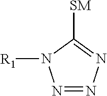
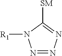
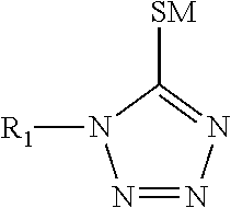
TABLE 1COMPONENTFORMULATION IFORMULATION IISilver ions from silver 60 g / L 60 g / Lmethane sulfonateTin ions from tin methane 15 g / L 15 g / LsulfonateMethane sulfonic acid162 g / L162 g / L1-(2-Dimethylaminoethyl)-150 g / L150 g / L5-mercapto-1,2,3,4-tetrazole3,6-dithiaoctane-1,8-diol 22 g / L04,4-thiodiphenol0 2 g / LAmine oxide surfactant 3 g / L 3 g / LHydroquinone 1.2 g / L  1.2 g / L monosulfonic acid,potassium salt

[0055]Electrolysis of formulation I was then performed. The test was done to show the electrochemical stability of the bath. A brass panel 7.5 cm×10 cm was weighed and then secured in the plating tank. A low current density of 2 ASD was applied to the panel for 15 minutes. The panel was removed from the plating tank and weighed. The amount of silver / tin plated during the 15 minutes was determined. The quantity of electricity was also recorded in ampere hou...

example 2

[0057]The two formulations in Table 1 were used to electroplate a silver / tin alloy on brass, copper, copper / beryllium alloy, copper / nickel alloy, copper / tin alloy, nickel coated brass and nickel coated copper panels. Each panel was 7.5 cm×10 cm. The thickness of the panels was 0.25 mm. The nickel coated brass and nickel coated copper panels contained a silver strike layer of less than 100 nm to promote adhesion of the silver / tin layer to the nickel. The silver strike layer had been electroplated on the panels using a silver strike bath containing 2 g / L silver ions, 15 g / L 3,6-dithia-1,8-octanediol, 67 g / L methane sulfonic acid. Electroplating had been done for 0.5 ASD to 1 ASD for 10 seconds to 30 seconds.

[0058]The panels were placed in plating tanks containing either Formulation I or Formulation II. The temperatures of the baths were 50° C. and the anode was an iridium oxide insoluble anode. Each electrode was connected to a rectifier. Electroplating was done at 2 ASD. After the pa...

example 3

[0059]A brass cylinder 12 mm in diameter and 8 mm in height was mounted on the axis of an electrical motor and immersed in a plating bath containing Formulation I in Table 1. The motor was set to a rotation speed of 1000 rpm. An insoluble iridium oxide electrode was used as the anode. The electrodes were connected to a rectifier. The electroplating bath was agitated through rotation of the cathode and the bath temperature was maintained at 50° C. Electroplating was done at 0.5, 1, 2, 4, 6, 8, 10, 12, 14, 16, 18 and 20 ASD. The cylinder was changed when moving from one current density to another and the plating time was adjusted to keep the same film thickness. All of the silver / tin alloy deposits had a bright, shiny appearance over the current density range from 0.5 ASD to 16 ASD. Small burned edges were observed at 18 ASD and 20 ASD.

[0060]The silver and tin content of each deposit was determined by X-ray fluorescence (XRF) analysis using a FISCHERSCOPE X-Ray model XDV-SD from Helmu...


PUM

PropertyMeasurementUnit
weight ratioaaaaaaaaaa
current densityaaaaaaaaaa

Abstract

Silver and tin alloy electroplating baths include complexing agents which enable the electroplating of either silver rich or tin rich alloys. The silver and tin alloy electroplating baths are substantially free of lead. They may be used to electroplate silver and tin alloys in the manufacture of electronic components such as electrical connectors, finishing layers for metallic substrates, decorative applications and solder bumps.

Description

FIELD OF THE INVENTION[0001]The present invention is directed to electroplating baths of silver and tin alloys and methods of electroplating the silver and tin alloys. More specifically, the present invention is directed to electroplating baths of silver and tin alloys and methods of electroplating the silver and tin alloys where the electroplating baths contain complexing agents which enable silver rich or tin rich alloys.BACKGROUND OF THE INVENTION[0002]There are two categories of silver and tin alloys. One is silver based or silver rich silver / tin alloys where the silver content is above 50%. Such alloys posses higher hardness and higher wear resistance compared to pure silver and are used in decorative applications. Due to their excellent electrical conductivity they may also be used in electronic connectors to reduce the amount of hard gold. Hard gold is used in electronic connectors as a contact material finish because it has good wear and corrosion resistance. The hard gold p...

Claims


Application Information

Patent Timeline
Patent Type & Authority Patents(United States)
IPC IPC(8): C25D3/60H01L23/00C25D3/64C25D5/50C25D7/12
CPCC25D3/60C25D3/64C25D5/505C25D7/123H01L24/11H01L24/13H01L24/03H01L24/05H01L2224/0345H01L2224/0361H01L2224/03452H01L2224/03462H01L2224/03912H01L2224/0401H01L2224/05111H01L2224/05147H01L2224/05171H01L2224/05611H01L2224/05647H01L2224/05655H01L2224/1147H01L2224/11462H01L2224/11901H01L2224/13111H01L2924/01322H01L2924/01047H01L2924/00014H01L2924/00
Inventor FOYET, ADOLPHECLAUSS, MARGITZHANG-BEGLINGER, WANWOERTINK, JULIAQIN, YIPRANGE, JONATHANLOPEZ MONTESINOS, PEDRO O
Owner ROHM & HAAS ELECTRONICS MATERIALS LLC
Learn More